Stretcher for spine surgery

A surgical and stretcher technology, applied in the field of stretchers, can solve the problems of being susceptible to tightening force, falling of the supporting woven fabric, no design, etc., and achieve the effect of avoiding excessive angle, increasing comfort, and good support.

Inactive Publication Date: 2017-03-29
LUOYANG ORTHOPEDIC TRAUMATOLOGICAL HOSPITAL
7 Cites 11 Cited by

AI-Extracted Technical Summary

Problems solved by technology

[0002] Stretcher is a commonly used medical equipment, which is used to carry the wounded and injured in the rescue process. However, the traditional stretcher structure is simple and thin, and the structure of supporting woven fabric is set between the two poles. Although this structure can meet the general needs in use However, when the patient is lifted, the middle of the supporting woven fabric is under a large f...

Abstract

The invention discloses a stretcher for spine surgery. The stretcher comprises a device main frame, wherein both sides of the device main frame are hinged with side frames by virtue of hinges; a group of limiting plates are arranged at the lower sides of the side frames; a group of mounting frames are arranged at the lower side of the device main frame; a group of rotating shafts are arranged on the mounting frames; the rotating shafts are matched with rotary square sleeves in rotary mode; the rotary square sleeves are connected to supporting legs by virtue of supporting springs; universal wheels are arranged at the lower ends of the supporting legs; an air cushion is arranged at the upper side of the device main frame; an inflator, which is matched with the air cushion, is arranged at one end of the device main body; a group of handles are arranged at each of two ends of the device main frame; and clamping block sliding buttons and pull arm sliding buttons are arranged on the handles in a sliding mode. The stretcher for the spine surgery is convenient to operate, and the stretcher, when used, can relieve burden of medical personnel, so that the medical personnel can carry a patient with lower physical power consumed; meanwhile, the patient can be protected well; and the stretcher can effectively prevent the body of the patient from getting displaced, so that the occurrence of secondary injury can be prevented.

Application Domain

Technology Topic

Spine surgeryHinge angle +3

Image

  • Stretcher for spine surgery
  • Stretcher for spine surgery
  • Stretcher for spine surgery

Examples

  • Experimental program(1)

Example Embodiment

[0023] The technical solutions in the embodiments of the present invention will be clearly and completely described below in conjunction with the accompanying drawings in the embodiments of the present invention. Obviously, the described embodiments are only a part of the embodiments of the present invention, rather than all the embodiments. Based on the embodiments of the present invention, all other embodiments obtained by those of ordinary skill in the art without creative work shall fall within the protection scope of the present invention.
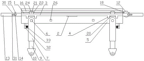
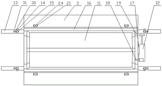
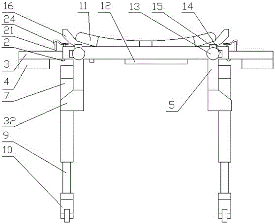
[0024] See Figure 1-8 , The present invention provides a technical solution: a stretcher for spinal surgery, comprising a device main frame 1, both sides of the device main frame 1 are hinged with a side frame 3 through a hinge 2, and a set of Limiting plate 4, the lower part of the main frame 1 of the device is provided with a set of mounting frames 5, the mounting frame 5 is provided with a set of rotating shafts 6, the rotating shafts 6 and the rotating square sleeve 7 are rotatably matched, the rotating square sleeve 7 passes The support spring 8 is connected to the leg 9, the lower end of the leg 9 is provided with a universal wheel 10, the upper part of the device main frame 1 is provided with an air cushion 11, and one end of the device main frame 1 is provided with an air cushion 11 adapted to A set of handles 13 are provided at both ends of the main frame 1 of the device. The handle 13 is slidably provided with a block slide button 14 and a pull arm slide button 15. Both sides of the device main frame 1 A ramp plate 16 is provided, the ramp plate 16 is adapted to the air cushion 11 to hold up the side of the air cushion 11, an air pump rack 17 is provided at one end of the main frame 1 of the device, and the air pump 12 is installed On the air cylinder frame 17, the air pump 12 is matched with the one-way air inlet 18 on the air cushion 11, one end of the air cushion 11 is also provided with an air release nozzle 19, and the outer side of the rotating square sleeve 7 is made of stainless steel Made of material, the side frame 3 is provided with a magnetic plate 20 at a position between the limit plates 4, and the magnetic plate 20 is suction-fitted with the outer side of the rotating square sleeve 7, and the side frame 3 A set of pull plates 21 are provided. A set of pull arm supports 22 are provided on both sides of the main frame 1 of the device. The pull arm supports 22 are hinged with the pull arm 24 through a torsion spring shaft 23. One end of the pull arm 24 is connected to the The pull plate 21 is matched, the other end of the pull arm 24 is connected to the pull arm slide button 15 through a pull arm pull cord 25, and a set of sloped surface blocking blocks 26 are provided on the side of the mounting frame 5, the sloped surface blocking blocks 26 is matched with the mounting frame 5 through a return spring 27, the slope block 26 is connected to the block slide button 14 by a block pull cord 28, and the handle 13 is provided with a pull arm slide groove 30 and a card Block sliding groove 31, the pull arm sliding button 15 is slidingly fitted with the pulling arm sliding groove 30, the clamping block sliding button 14 is slidingly fitted with the clamping block sliding groove 31, the pull arm pull cord 25 and the The clip pull cords 28 are all arranged in the device main frame 1 and cooperate with the rollers 29 arranged in the device main frame 1. A set of shock-absorbing plates 32 are arranged at the lower part of the mounting frame 5, and the shock-absorbing plates 32 A shock-absorbing spring 33 is provided on one side, and the shock-absorbing spring 33 is adapted to the rotating square sleeve 7, and the rotating square sleeve 7 is provided with a mounting groove 34 inside, and the supporting spring 8 is arranged in the mounting groove 34 Inside, a block groove 35 is opened on one side of the rotating square sleeve 7, and the block groove 35 is adapted to the slope block 26.
[0025] Working principle: When using the spine surgery stretcher, two medical staff cooperate, each holding the handle 13 at one end of the device main frame 1 lifts the device to move, moves the device main frame 1 to the vicinity of the patient, and then uses the inflator 12 pairs of air cushions 11 are inflated. After the air cushion 11 is inflated, the medical staff move the patient to the air cushion 11 on the main frame 1 of the device. The air cushion 11 can increase the patient’s comfort when lying down, and at the same time can reduce The main frame 1 of the device is a rigid plate-like structure, which can provide good support. The patient lies on the main frame 1 of the device, and the main frame 1 of the device is not deformed, which avoids the floating deformation of the traditional cloth stretcher. This causes the patient’s torso to be difficult to fix. The rotating square sleeve 7 is placed horizontally at the beginning, and the rotating square sleeve 7 is attached to the side of the mounting frame 5. After the patient lies down, the medical staff can grasp the handle 13 to hold the device The frame 1 is lifted to move the patient. When moving to an ambulance or other rescue place, it can be directly lifted to the destination. When the distance is far, the medical staff can use the index finger to pull the block on the handle 13 The slide button 14, the clip slide button 14 is pulled back in the clip slide groove 31, and then the clip pull cord 28 connected with the clip slide button 13 is pulled, and the other end of the clip pull cord 28 is locked with the slope surface. If the block 26 is connected, the ramp block 26 is pulled into the mounting frame 5, and the block groove 35 on the rotating square sleeve 7 is matched with the ramp block 26, and the ramp block 26 is pulled back to the mounting frame 5. After being inside, the block groove 35 loses the limiting function of the slope block 26. At this time, the rotating square sleeve 7 will rotate and fall under the action of gravity. When falling, the rotating square sleeve 7 will be affected by the elastic force of the damping spring 33 It is buffered to prevent the angle of the rotating square sleeve 7 from being too large and hurting the legs of the medical staff. After the medical staff releases the block sliding button 14, the slope block 26 will reset under the elastic force of the return spring 27, and the square sleeve can be rotated. 7 After being stabilized, the medical staff can pull the arm slide button 15 with the thumb. The arm slide button 15 is connected to the arm rope 25. The arm slide button 15 drives the arm rope 25 so that the arm rope 25 overcomes the torsion spring axis. The rebound force of 23 pulls down one end of the pull arm 24, and the other end of the pull arm 24 is tilted. At this time, the pull plate 21 loses the pulling action of the pull arm 24, and the side frame 3 falls under the action of gravity, and the limit plate 4 and The position of the rotating square sleeve 7 is adapted after it hangs down. After falling, the limit plate 4 is matched with the rotating square sleeve 7. The magnetic plate 20 and the side of the rotating square sleeve 7 are adsorbed to complete the fixing of the side frame 3, and then the rotating square sleeve 7 Can not swing under the limit effect of the limit plate 4, the whole device can contact the ground by rotating the square sleeve 7 and the support of the legs 9. The roller 29 can be set in the device main frame 1, and the roller 29 can reduce the jam The frictional force of the block rope 28 and the arm rope 25 prevents the block rope 28 and the arm rope 25 from directly rubbing against the corners of the main frame 1 of the device. The number of rollers 29 can be installed according to the actual situation. The position is enough to reduce friction. The use of universal wheel 10 makes the movement of the device convenient and labor-saving. Medical staff only need to pull the handle 13 to make the device move, which greatly reduces physical consumption. The time support spring 8 can play a shock-absorbing effect to prevent the patient from being strongly impacted when the main frame 1 of the device is bumped due to uneven road. At the same time, when the medical staff lifts the handle 13 to make the device pass through the road with bad road conditions, The direction wheel 10 is still in contact with the ground, and the support spring 8 can provide a certain lifting force, which reduces the weight of the medical staff.
[0026] Although the embodiments of the present invention have been shown and described, those of ordinary skill in the art can understand that various changes, modifications, and substitutions can be made to these embodiments without departing from the principle and spirit of the present invention. And variations, the scope of the present invention is defined by the appended claims and their equivalents.

PUM

no PUM

Description & Claims & Application Information

We can also present the details of the Description, Claims and Application information to help users get a comprehensive understanding of the technical details of the patent, such as background art, summary of invention, brief description of drawings, description of embodiments, and other original content. On the other hand, users can also determine the specific scope of protection of the technology through the list of claims; as well as understand the changes in the life cycle of the technology with the presentation of the patent timeline. Login to view more.

Similar technology patents

Control method of air conditioner and air conditioner

Owner:GD MIDEA AIR-CONDITIONING EQUIP CO LTD +1

Classification and recommendation of technical efficacy words

  • Improve comfort
  • Good support

Treatment of teeth by aligners

InactiveUS20060275731A1Improve comfortReduce treatment time and costImpression capsAdditive manufacturing apparatusDental treatmentsOrthodontics
Owner:ALIGN TECH

Fan

Owner:UNIVERSAL SAFETY RESPONSE +1

Cleaning method and device for indoor heat exchanger of air conditioner

ActiveCN104848738AAchieve high temperature sterilization functionImprove comfortCleaning heat-transfer devicesSpace heating and ventilation safety systemsFrostEngineering
Owner:GREE ELECTRIC APPLIANCES INC

Sports Garment

Owner:GROSSE STEFANI
Why Eureka
Try Eureka