Multi-channel cooling bed charging device and cooling bed

A multi-channel, cooling bed technology, applied in cooling beds, metal processing equipment, metal rolling, etc., can solve the problem that the steel device on the cooling bed cannot be divided into steel, etc., and achieve the effect of simple structure, novel concept, and reasonable and compact layout

Active Publication Date: 2017-03-29
HUATIAN NANJING ENG & TECH CORP MCC
View PDF7 Cites 2 Cited by
  • Summary
  • Abstract
  • Description
  • Claims
  • Application Information

AI Technical Summary

Problems solved by technology

[0003] In order to overcome the defects of the prior art, the object of the present invention is to provide a steel device on the multi-channel cooling bed to solve the problem that the steel device on the cooling bed cannot separate steel during split rolling

Method used


Image

  • Multi-channel cooling bed charging device and cooling bed
  • Multi-channel cooling bed charging device and cooling bed
  • Multi-channel cooling bed charging device and cooling bed

Examples


Embodiment 1

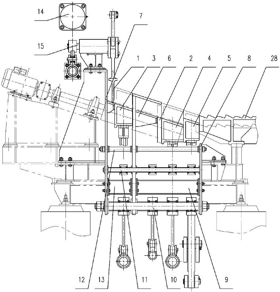
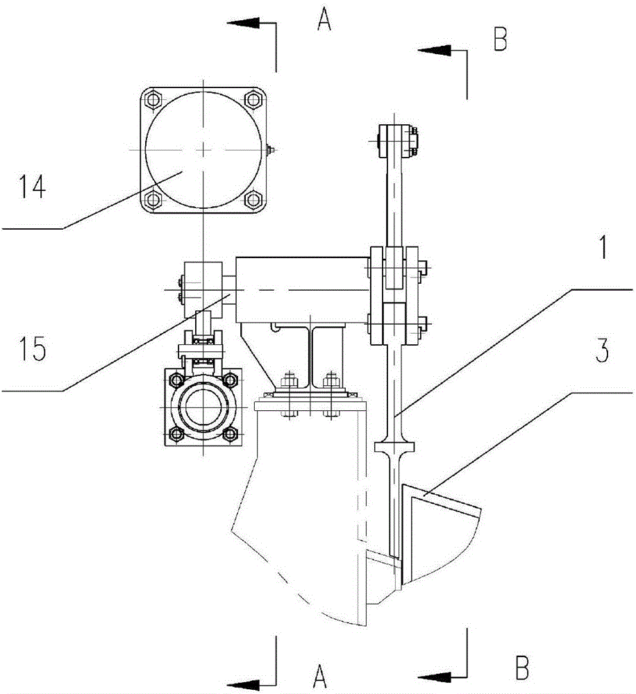
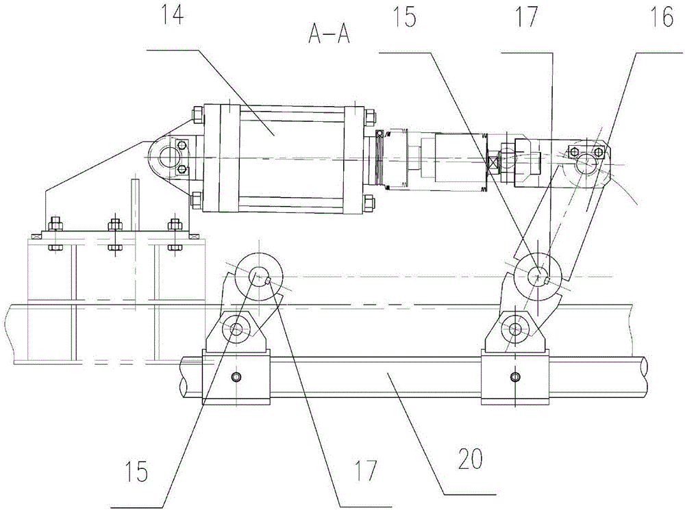
[0035] For larger gauge rolling pieces (such as round steel, angle steel, etc.) that do not need to be split and rolled, such as Image 6 As shown, the method of loading steel is as follows:

[0036] In the first step, the first skirt plate 1 and the first skirt plate 2 are both located at the high position, and the third skirt plate 3, the fourth skirt plate 4 and the fifth skirt plate 5 are all located at the low position. At this time, the first rolling piece #1 Enter into the third steel inlet channel formed by the first skirt plate 2 and the guide plate 6, and stop quickly after braking;

[0037] In the second step, the first skirt board 1 is at a high position, and the second skirt board 2 moves to a low position. At this time, the top slopes of the guide board 6, the first skirt board 2 and the fourth skirt board 4 are on the same slope and stay on the first The rolling piece #1 in the third steel channel slips down along this inclined plane and stays in the fourth steel cha...

Embodiment 2

[0046] For rolling pieces that need to be split and rolled, such as Figure 7 As shown, the method of loading steel is as follows:

[0047] In the first step, the first skirt plate 1 and the fifth skirt plate 5 are both located at the high position, and the second skirt plate 2, the third skirt plate 3, and the fourth skirt plate 4 are all located at the low position. At this time, the rolled one The rolling piece B1 enters the second steel inlet channel formed by the third skirt plate 3 and the guide plate 6, and stops after rapid braking; another rolling piece A1 that is cut and rolled enters the fourth skirt plate 4 and the fifth skirt plate 5 In the fourth steel channel formed, stop quickly after braking;

[0048] In the second step, the first skirt plate 1 is moved to the low position, the second skirt plate 2 is moved to the high position, and the third skirt plate 3 and the fourth skirt plate 4 are both moved to the middle position. The piece B2 enters the first fixed seat ...


PUM


Abstract

The invention discloses a multi-channel cooling bed charging device and a cooling bed. The multi-channel cooling bed charging device is arranged in front of a straightening board and comprises a box type frame, a first apron board unit, a second apron board unit, a third apron board unit, a fourth apron board unit and a fifth apron board unit. The box type frame is provided with a first fixing seat, a second fixing seat, a guide plate, a shaft I and a shaft II, wherein the shaft I and the shaft II connect the first fixing seat, the second fixing seat and the guide plate; and the first apron board unit, the second apron board unit, the third apron board unit, the fourth apron board unit and the fifth apron board unit cooperate, an apron board of each apron board unit can reciprocate up and down independently through action of a corresponding air cylinder, when the different apron boards are located in the different positions, different steel inlet channels can be formed between the apron boards as well as between the apron boards and supports, and therefore, the purpose of entering of multiple rolled pieces of the charging device at the same time is achieved.

Description

Technical field [0001] The invention belongs to the technical field of steel rolling machinery and equipment, in particular to a new type of multi-channel cooling bed steel device, and also relates to a cooling bed with the above-mentioned steel loading device. Background technique [0002] In the steel rolling workshop, the cooling bed is one of the key equipment on the production line, used for lateral transportation and cooling of double-length finished products. The cooling bed currently in use includes a steel loading device, a stepping rack bed surface, a aligning roller table, and a steel lowering device. The steel loading device is composed of an input roller table, an upper steel skirt board and a straightening board, and the upper steel skirt board is a key component. , Used to quickly brake the high-speed running rolling pieces, and transport the rolling pieces to the straightening plate through the upper steel skirt plate. The traditional upper steel skirt plate trans...

Claims


Application Information

Patent Timeline
Patent Type & Authority Applications(China)
IPC IPC(8): B21B43/00
CPCB21B43/003
Inventor 潘天成陈龙朱国民
Owner HUATIAN NANJING ENG & TECH CORP MCC
Why Eureka
Try Eureka