
Long-span welding belt threading mechanism, welding belt supply device and stringer

A long-span, welding strip technology, used in auxiliary devices, welding equipment, auxiliary welding equipment, etc., can solve the interference and distance of the welding strip, and the welding strip will fall after it is loosened or used up and affects other processes. Problems such as work and welding ribbons intertwined with each other

Active Publication Date: 2018-10-09
安徽联鹏智能装备有限公司
View PDF10 Cites 0 Cited by
  • Summary
  • Abstract
  • Description
  • Claims
  • Application Information

AI Technical Summary

Problems solved by technology

[0002] Since the development of the photovoltaic industry, automatic equipment for connecting solar cells for series welding, referred to as stringer, has been widely used. In this automated stringer, the structure of the ribbon supply device for supplying ribbon is also relatively Many, the welding strip device generally includes a welding strip roll mechanism, an overlapping part, and a welding strip threading mechanism, and generally the distance between the welding strip winding mechanism and the pulling welding strip threading mechanism is relatively long, and the welding strip is in the If it is loose or used up, it will fall down and affect the work of other processes. Therefore, a shaft is generally used to overlap the welding ribbon so as not to affect the work of other processes in the stringer or bring other hidden dangers to quality. The method is easy to control when the number of welding ribbons is small, but when the number of welding ribbons is large and the distance between the welding ribbon coiling mechanism and the welding ribbon threading mechanism is farther, it cannot meet the requirements of the welding ribbon supply device. requirements, it is very easy to cause interference when wearing the ribbon and the ribbon is loose or entangled after being used up.

Method used


Image

  • Long-span welding belt threading mechanism, welding belt supply device and stringer
  • Long-span welding belt threading mechanism, welding belt supply device and stringer
  • Long-span welding belt threading mechanism, welding belt supply device and stringer

Examples


Embodiment Construction

[0029] In order to more clearly illustrate the technical solutions of the embodiments of the present invention, the following will briefly introduce the accompanying drawings that need to be used in the embodiments. Obviously, the accompanying drawings in the following description are some embodiments of the present invention. Ordinary technicians can also obtain other drawings based on these drawings on the premise of not paying creative work.

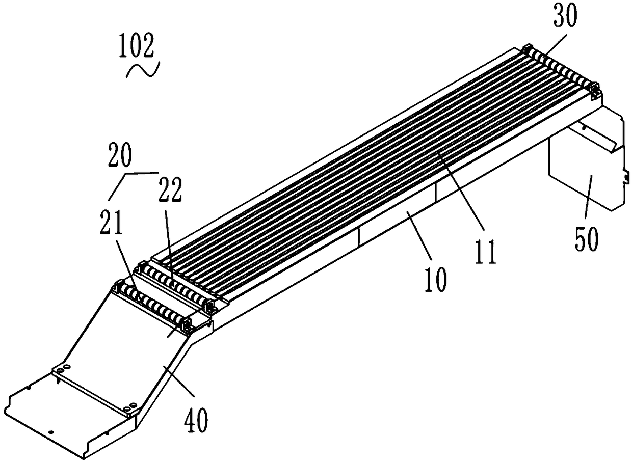
[0030] see figure 1 , the embodiment of the present invention provides a long-span welding ribbon threading mechanism 102, including a center beam 10, an input guide mechanism 20 arranged at the input end of the center beam 10, an output guide mechanism 30 arranged at the output end of the center beam 10, The input guide mechanism 20 and the output guide mechanism 30 are all fixedly connected with the middle beam 10, the middle beam 10 is a strip shaped body arranged along a straight line direction, and on the upper surface of the mid...


PUM


Abstract

The invention provides a long-span welding strip threading mechanism. The long-span welding strip threading mechanism comprises a middle beam, an input guide mechanism and an output guide mechanism, wherein a plurality of containing grooves for containing welding strips are formed in the upper surface of the middle beam along the length direction of the middle beam; the input guide mechanism is also provided with a plurality of inlet guide grooves for containing the welding strips; the output guide mechanism is also provided with a plurality of outlet guide grooves for containing the welding strips. According to the long-span welding strip threading mechanism provided by the invention, the grooves with certain depth are formed in the middle beam, and the grooves for containing the welding strips are also formed in the input guide mechanism and the output guide mechanism; the depth of the grooves of the input guide mechanism and the depth of the grooves of the output guide mechanism are set according to the depth of the grooves of the middle beam, so that the welding strip is controlled to be transported at upper ends of bottom surfaces of the grooves in the middle beam all the time; when the welding strip is loosened or after the welding strip is used up, the welding strip is located in the grooves of the middle beam all the time and mutual winding is not caused.

Description

technical field [0001] The invention relates to the technical field of ribbon supply and welding for solar cells, in particular to a long-span ribbon threading mechanism, a ribbon supply device and a stringer. Background technique [0002] Since the development of the photovoltaic industry, automatic equipment for connecting solar cells for series welding, referred to as stringer, has been widely used. In this automated stringer, the structure of the ribbon supply device for supplying ribbon is also relatively Many, the welding strip device generally includes a welding strip roll mechanism, an overlapping part, and a welding strip threading mechanism, and generally the distance between the welding strip winding mechanism and the pulling welding strip threading mechanism is relatively long, and the welding strip is in the If it is loose or used up, it will fall down and affect the work of other processes. Therefore, a shaft is generally used to overlap the welding ribbon so a...

Claims


Application Information

Patent Timeline
Patent Type & Authority Patents(China)
IPC IPC(8): B23K37/00
CPCB23K37/00B23K2101/36
Inventor 马成虎
Owner 安徽联鹏智能装备有限公司
Learn More