Sewage lifting equipment for solid-liquid separation

A technology for sewage lifting and solid-liquid separation, applied in waterway systems, water supply devices, drainage structures, etc., can solve the problems of thick cushion, inconvenient management, poor sanitation, etc., and achieve the effect of prolonging the service life

Inactive Publication Date: 2018-04-17
合肥华福土工合成材料有限公司
View PDF0 Cites 0 Cited by
  • Summary
  • Abstract
  • Description
  • Claims
  • Application Information

AI Technical Summary

Problems solved by technology

There are three disadvantages in the first method: first, solid matter such as feces in the sewage, which is not cleaned for a long time, is easy to cause blockage; second, because the sump is shallow, the operation of the submersible sewage pump that starts and stops according to the water level is not reliable; The third is that the airtightness of the sump is not good, there is an odor, and the sanitary condition is not good
The second method is to build pump wells outdoors, the depth is deeper, the investment is larger, and the management is inconvenient
In this way, the thickness of the cushion is thicker, sometimes up to 350-400mm, which brings difficulties to the use of the toilet and the layout of the building.
[0003] At present, the domestic sewage is usually stored in a sewage tank first, and then the sewage is lifted to the sewage treatment equipment for treatment through the water pump. The domestic sewage contains a lot of dirt, and the dirt will be deposited in the sewage tank, and some dirt will enter In the water pump impeller, it is easy to cause entanglement and blockage, which makes the water pump unable to work normally and shortens the service life of the water pump. If there is too much dirt deposited, it needs to be cleaned up in time to prevent the sewage from overflowing and polluting the surrounding environment. In view of this, we propose a solid Liquid separation sewage lifting equipment

Method used


Image

  • Sewage lifting equipment for solid-liquid separation

Examples


Embodiment Construction

[0017] The following will clearly and completely describe the technical solutions in the embodiments of the present invention with reference to the accompanying drawings in the embodiments of the present invention. Obviously, the described embodiments are only some, not all, embodiments of the present invention. Based on the embodiments of the present invention, all other embodiments obtained by persons of ordinary skill in the art without making creative efforts belong to the protection scope of the present invention.

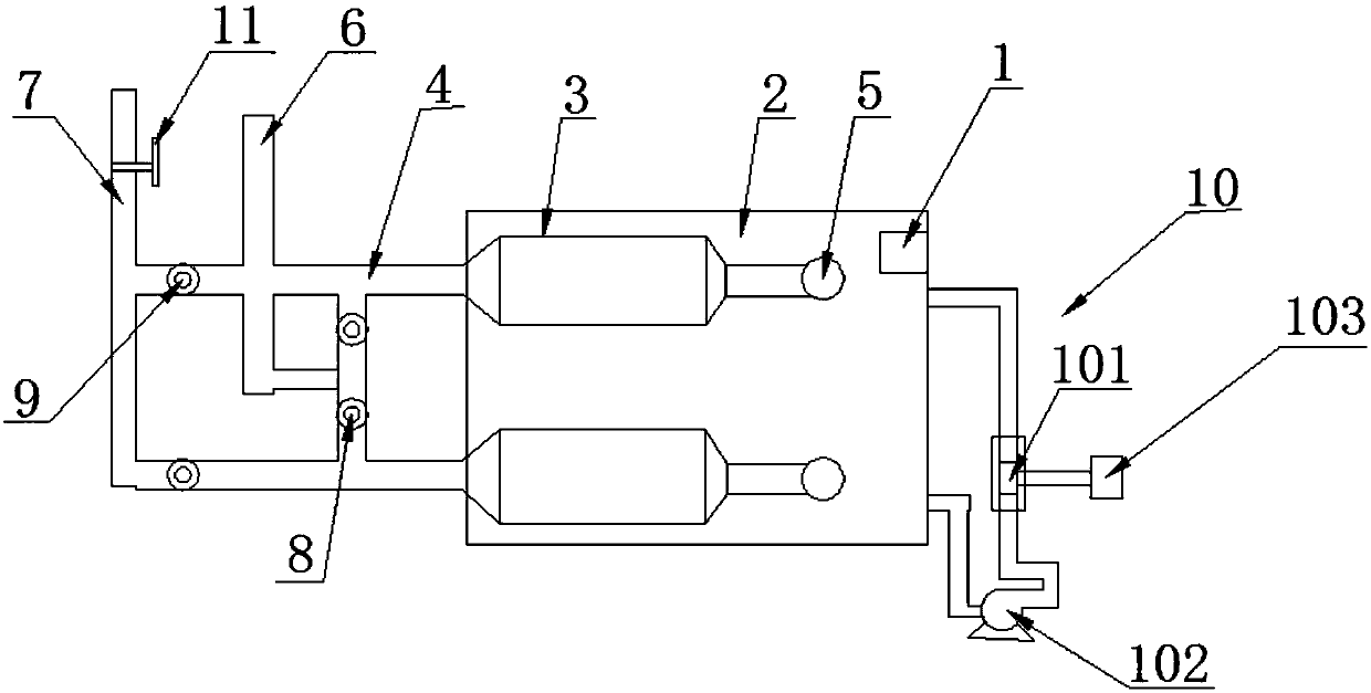
[0018] see figure 1 , the present invention provides a technical solution:

[0019] A sewage lifting device for solid-liquid separation, including a sewage tank 2, a solid-liquid separator 3 is provided in the sewage tank 2, a number of solid-liquid separators 3 are provided in the sewage tank 2, and the solid-liquid separator 3 adopts a suspension type solid-liquid separation A number of solid-liquid separators 3 are arranged in parallel between the water in...


PUM


Abstract

The present invention relates to the technical field of wastewater treatment devices, in particular to a solid-liquid separation sewage lifting equipment, including a sewage tank, a solid-liquid separator is arranged in the sewage tank, one end of the solid-liquid separator is connected to the first water flow channel, solid-liquid The other end of the liquid separator is connected to the submersible sewage pump, the upstream of the first water flow channel is connected to the water inlet pipe and the sewage pipe, a first check valve is provided between the water inlet pipe and the first water flow channel, and a As for the second one-way valve, a self-priming device connected with the sewage tank is provided outside the sewage tank. In the present invention, a number of solid-liquid separators are arranged in the sewage tank, and several solid-liquid separators are arranged in parallel between the water inlet pipe and the sewage pipe. The multiple solid-liquid separators can be used to respectively store sewage and waste water in the sewage tank. The sewage in the sewage tank is discharged, and at the same time, it works uninterruptedly, which improves the work efficiency.

Description

technical field [0001] The invention relates to the technical field of wastewater treatment devices, in particular to a lifting device for solid-liquid separation sewage. Background technique [0002] In the basement of the building, building toilets is a common situation in the design, and the sewage generated cannot flow out by itself. At this time, no matter how many sanitary ware are installed in the bathroom, there are two more traditional methods: one method is to set up a sump under the basement floor, collect the sewage from the sanitary ware together, and use a submersible sewage pump to lift and discharge it to Outdoor underground sewage pump well; Another kind of method is all the sewage of toilet is discharged into outdoor underground sewage pump well by gravity, promotes and discharges into the sewage inspection well near the pump well with submersible sewage pump. There are three disadvantages in the first method: first, solid matter such as feces in the sewag...

Claims


Application Information

Patent Timeline
Patent Type & Authority Applications(China)
IPC IPC(8): E03F5/22
CPCE03F5/22
Inventor 武全福
Owner 合肥华福土工合成材料有限公司
Why Eureka
Try Eureka