Terminal connection assembly and container
A terminal connection, container technology, applied in the direction of connection, parts of connecting devices, connectors of computer peripheral equipment, etc.
- Summary
- Abstract
- Description
- Claims
- Application Information
AI Technical Summary
Problems solved by technology
Method used
Image

Examples
no. 1 example
[0094] A-1. The overall structure of the printing material supply system:
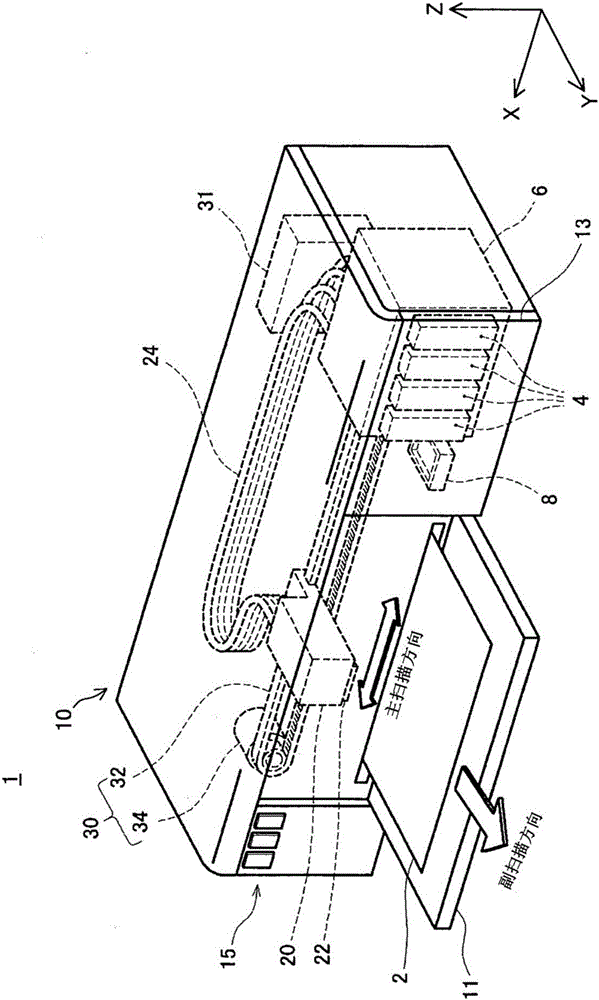
[0095] figure 1 It is a perspective view showing the configuration of the printing material supply system 1 . exist figure 1 In , three spatial axes that are orthogonal to each other are drawn, that is, the X axis, the Y axis, and the Z axis. The directions pointed by the arrows of the X-axis, Y-axis, and Z-axis represent positive directions along the X-axis, Y-axis, and Z-axis, respectively. The positive directions along the X-axis, Y-axis, and Z-axis are respectively referred to as +X-axis direction, +Y-axis direction, and +Z-axis direction. Directions opposite to the directions pointed by the arrows of the X-axis, Y-axis, and Z-axis are negative directions along the X-axis, Y-axis, and Z-axis, respectively. The negative directions along the X-axis, Y-axis, and Z-axis are referred to as -X-axis direction, -Y-axis direction, and -Z-axis direction, respectively. The directions along the X-axis, Y-...
no. 2 example
[0198] The printing material supply system 1A of the second embodiment is compared with the printing material supply system 1 of the first embodiment, the terminal accommodating chamber 900 of the container 4 (refer to Figure 27 ) have different structures, but are otherwise the same. In the description of the second embodiment, the same reference numerals are attached to the same structures as those of the first embodiment, and descriptions thereof are omitted. In addition, the structure of the printer 10 is the same as that of the first embodiment.
[0199] Figure 38 It is an external perspective view of the vicinity of the terminal accommodating part 900A. Figure 39 It is a figure which looked at the vicinity of 900 A of terminal accommodating parts from the +Z-axis direction side. Figure 40 It is a figure which looked at the vicinity of 900 A of terminal accommodating parts from the -X-axis direction side. Figure 41 It is a front view of terminal accommodating par...
no. 3 example
[0213] The printing material supply system 1B of the third embodiment differs from the printing material supply system 1A of the second embodiment in the structure of the terminal accommodating portion 900B, but is the same except for that.
[0214] use Figure 44 The detailed structure of the terminal accommodating portion 900B of the third embodiment will be described. Figure 44 It is an external perspective view of the vicinity of the terminal accommodating part 900B.
[0215] like Figure 44 As shown, in the third embodiment, the protrusion 915A protrudes from the rear wall 986 in the −Y-axis direction. The convex portion 915A has a first convex portion 915At located on the +X-axis direction side relative to the circuit board 50 in the X-axis direction and a second convex portion 915Aw located on the −X-axis direction side relative to the circuit board 50 in the X-axis direction.
[0216] The first protrusion 915At has (i) a substantially rectangular columnar member 91...
PUM
 Abstract
Description
Claims
Application Information
 - R&D
- Intellectual Property
- Life Sciences
- Materials
- Tech Scout
- Unparalleled Data Quality
- Higher Quality Content
- 60% Fewer Hallucinations
Browse by: Latest US Patents, China's latest patents, Technical Efficacy Thesaurus, Application Domain, Technology Topic, Popular Technical Reports.
© 2025 PatSnap. All rights reserved.Legal|Privacy policy|Modern Slavery Act Transparency Statement|Sitemap|About US| Contact US: help@patsnap.com