Three-dimensional shock insulation device capable of adjusting vertical initial stiffness

A technology of initial stiffness and vertical seismic isolation, applied in the direction of earthquake resistance, building components, building types, etc., can solve the problems of shortened effective working length of springs, deformation of two sets of disc springs, and reduced isolation costs, so as to reduce wind resistance Anti-vibration cost, small vertical length, effect of suppressing shaking

Inactive Publication Date: 2017-03-29
NANJING DADE DAMPING TECH CO LTD
View PDF9 Cites 5 Cited by
  • Summary
  • Abstract
  • Description
  • Claims
  • Application Information

AI Technical Summary

Problems solved by technology

Although the scheme described in this patent application can improve the tensile strength of the three-dimensional seismic isolation device to resist the huge tension generated by the swaying or even overturning of high-rise buildings in an earthquake, the following deficiencies still exist: 1. The spring isolation The support can only be compressed for energy dissipation and shock absorption, but cannot be stretched for energy dissipation and shock absorption; 2. The spring isolation support cannot preset the initial stiffness, which is inconvenient to preset the seismic intensity and reduce the cost of isolation
However, this invention still has the following disadvantages: 1. The load connecting rod is balanced under the joint action of two groups of disc springs. Although the preload of the two groups of disc springs can be adjusted, no matter how they are adjusted, the The force of the disc spring on the load connecting rod is a set of equal and opposite forces. Just applying any external force on the load connecting rod will destroy this balance and deform the two sets of disc springs. Therefore, the 2. In this invention, two sets of disc springs must be used together to provide damping when the damper is under compression or tension load, which not only causes a certain waste, but also makes the damper greatly increased in length
It can be seen that although the stiffness of the spring in the patent application scheme can be changed, the effective working length of the spring is not only significantly shortened, but also can only be compressed for energy consumption and vibration reduction, and cannot be stretched for energy consumption and vibration reduction.

Method used


Image

  • Three-dimensional shock insulation device capable of adjusting vertical initial stiffness
  • Three-dimensional shock insulation device capable of adjusting vertical initial stiffness
  • Three-dimensional shock insulation device capable of adjusting vertical initial stiffness

Examples


example 1

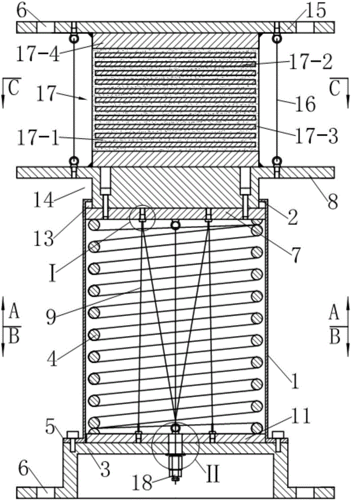
[0040] see figure 1 , the three-dimensional seismic isolation bearing in this example is composed of laminated rubber isolation bearings and vertical isolation bearings connected in series up and down.

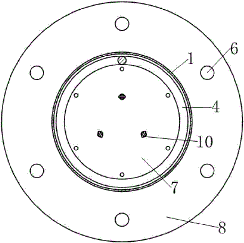
[0041] see figure 1 and Figure 4 , the laminated rubber shock-isolation bearing includes an upper connection plate 15, a lower connection plate 8, a laminated rubber pad 17 clamped between the upper and lower connection plates and six tensile steel wire ropes 16; wherein, the upper connection Both the plate 15 and the lower connecting plate 8 are disc-shaped, and the edge of the upper connecting plate 15 is provided with mounting holes 6; the main body of the laminated rubber pad 17 is alternately laminated by a layer of rubber 17-1 and a layer of steel plate 17-2. It is formed by molding vulcanization after being combined, and a rubber protection layer 17-3 is naturally formed around it during the molding vulcanization process. The upper and lower ends of the main body ...

example 2

[0061] see Figures 12 to 15 , on the basis of example 1, this example has mainly carried out the following improvements: (1) increasing the number of preloaded steel wire ropes 9 from three to six; (3) correspondingly changing the described back pressure device into:

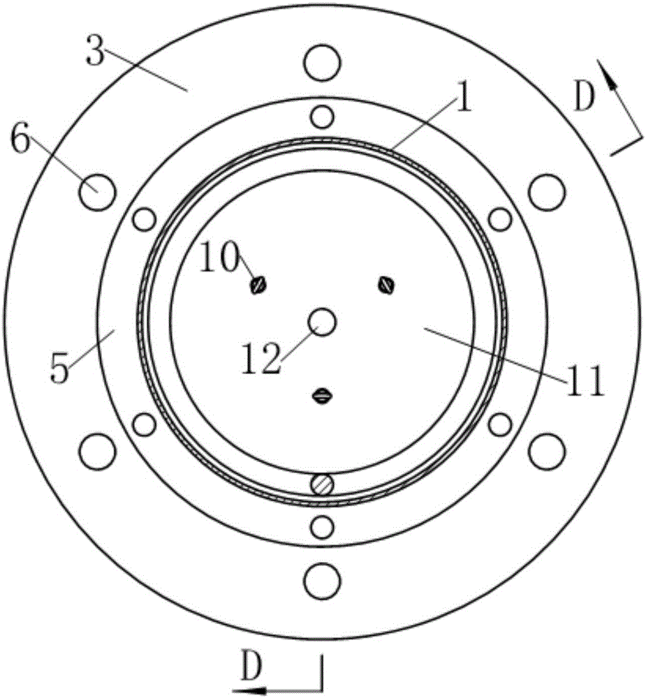
[0062] The back pressure device consists of six preloaded steel wire ropes 9, six U-shaped members 19 as wire rope direction changing elements, a floating back pressure steel plate 11, six eyebolts 10 for fixing one end of the preloaded steel wire ropes 9 and one fixed preloaded steel wire rope 9. The other end of the steel wire rope 9 is composed of a wire rope self-locking tensioning anchorage 18; wherein,

[0063] The floating anti-pressure steel plate 11 is arranged between the cylindrical helical compression spring 4 and the base 3;

[0064] Six U-shaped members 19 serving as wire rope redirection elements are symmetrically fixed on the driving platen 7 around the axis of the guide sleeve 1; see Figure...

example 3

[0069] see Figure 16-20 , this example has mainly carried out the following improvements on the basis of example 1: (1) replace the eyebolt 10 as the wire rope changing element with the fixed pulley 20; (2) change the described back pressure device accordingly to :

[0070] The anti-pressure device consists of four pre-compressed steel wire ropes 9, four fixed pulleys 20 as wire rope direction changing elements, a floating counter-pressure steel plate 11, four eyebolts 10 for fixing one end of the pre-compressed steel wire ropes 9 and one fixed pre-compressed steel wire rope 9. The other end of the steel wire rope 9 is composed of a wire rope self-locking tensioning anchor; wherein,

[0071] The floating anti-pressure steel plate 11 is arranged between the cylindrical helical compression spring 4 and the base 3;

[0072] Four fixed pulleys 20 as steel wire rope changing elements fix the lower surface of the driving platen 7 symmetrically around the axis of the guide sleeve ...


PUM


Abstract

The invention relates to a three-dimensional shock insulation device capable of adjusting the vertical initial stiffness. The three-dimensional shock insulation device comprises a vertical shock insulation support and a laminated rubber shock insulation support, and is characterized in that a back pressure device is further arranged in a guide sleeve of the vertical shock insulation support and comprises three or more pre-pressing steel wire ropes, steel wire rope direction-changing elements and steel wire rope self-locking tightening anchors which are numerically equal to the pre-pressing steel wire ropes, and a floating back pressure steel plate; the pre-pressing steel wire ropes are in broken line state; one end of each pre-pressing steel wire rope is symmetrically fixed on the floating back pressure steel plate around the axial line of the guide sleeve, and the other end of each pre-pressing steel wire rope bypasses the corresponding steel wire rope direction-changing element in a penetrating manner and then returns back; all the pre-pressing steel wire ropes are connected in parallel together to form a rope bundle which penetrates through the floating back pressure steel plate and is anchored on a pedestal through the steel wire rope self-locking tightening anchors; and the pre-pressing steel wire ropes are tightened to tension required by preset initial stiffness, so that a cylindrical helical compression spring is always clamped between a driving pressure plate and the floating back pressure steel plate.

Description

technical field [0001] The invention relates to a building anti-vibration (or shock) device, in particular to a three-dimensional shock-isolation device in which a sandwich steel plate rubber pad is connected in series with a vertical shock-isolation support. Background technique [0002] The seismic isolation device is an anti-seismic isolation device installed between the building and the foundation. The early seismic isolation devices were mainly two-dimensional isolation bearings (laminated rubber isolation bearings) composed of rubber and thin steel plates alternately laminated, which could only isolate the horizontal component of seismic waves. With the improvement of people's understanding of the multi-dimensional characteristics of earthquakes, three-dimensional seismic isolation devices have gradually attracted the attention of researchers in this field. The most common three-dimensional isolation device is composed of laminated rubber isolation bearings connected ...

Claims


Application Information

Patent Timeline
Patent Type & Authority Applications(China)
IPC IPC(8): E04B1/98E04H9/02
CPCE04H9/021
Inventor 谢韩涛刘汶津韩磊张少华
Owner NANJING DADE DAMPING TECH CO LTD
Why Eureka
Try Eureka