Painting device
A brushing and coating technology, applied in the direction of architecture, building structure, etc., to reduce the time of moving back and forth, reduce the difficulty of operation, and improve the efficiency of painting
- Summary
- Abstract
- Description
- Claims
- Application Information
AI Technical Summary
Problems solved by technology
Method used
Image
Examples
Embodiment 1
[0029] The embodiment of the present invention provides a brushing device for brushing the surface 800 to be brushed (see Figure 8 , Picture 9 , Figure 16 , Figure 17 ), where the coating 700 can be paint or latex, and the surface 800 to be painted can be a flat surface or a curved surface.
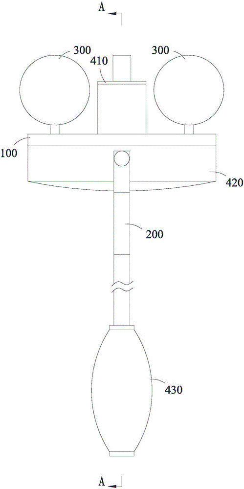
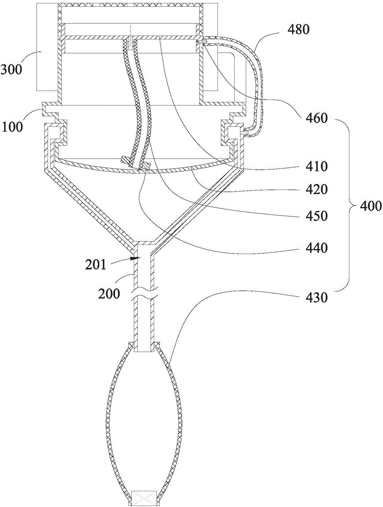
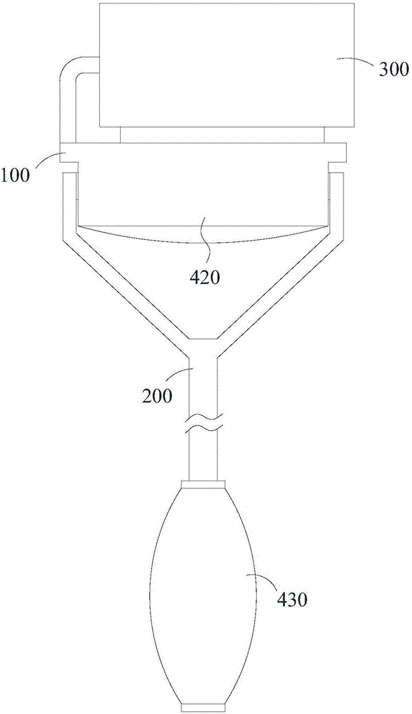
[0030] Such as Figure 1 to Figure 4 As shown, in this embodiment, the painting device includes a connecting seat 100, a handle 200 connected to the connecting seat 100, two roller brush cylinders 300 that are rotatably connected to the connecting seat 100 and arranged in parallel and spaced apart, and are used for supplying paint The supply assembly 400 of 700 has a discharge port 401 for the paint 700 to overflow. The discharge port 401 is located between the two roller brush cylinders 300 and faces the surface 800 to be brushed.
[0031] Based on the above structure, during use, first, the user grasps the handle 200 and allows the two roller brush cylinders 300 to abut the surface 800 to...
Embodiment 2
[0040] The difference between this embodiment and the first embodiment is as follows: Figure 5 to Figure 9 As shown, the discharging brush head 410 includes a brush head holder 411, a brush head cover 412, and a valve 413. The brush head holder 411 is provided with a brush holder inlet 411a matched with the feeding assembly 400, and a brush holder outlet 411b communicating with the brush holder inlet 411a. In this way, when the feeding assembly 400 supplies materials to the discharge brush head 410, the paint 700 will Enter from the brush holder entrance 411a, where the paint 700 can be paint or latex. The brush head cover 412 is fixed to the brush head base 411 and includes a discharging head 4121 and a connecting pipe 4122 connecting the brush head base 411 and the discharging head 4121. The discharging head 4121 is provided with a discharging port 401 communicating with the connecting pipe 4122, and the discharging port 401 is opened at the end of the discharging head 4121 ...
Embodiment 3
[0053] The difference between the second embodiment and the first embodiment is that Figure 10 to Figure 12 As shown, the storage container 420 is integrally arranged in the handle 200, and the feeding mechanism 430 includes a piston cavity integrally arranged in the handle 200 and together with the storage container 420, a piston rod 500 matched with the piston cavity, and arranged on the handle 200 and supply the paint 700 to enter the second one-way valve 600 of the storage container 420 from the outside. Among them, the handle 200 is directly rotatably connected with the connecting seat 100, and the angular relationship between the handle 200 and the working surface can be adjusted adaptively during the translation of the working surface, and the user can be within the length of the handle 200 without moving the position; The storage container 420 and the piston cavity are integrated in the handle 200, and the piston rod 500 can be used to transport the paint 700 to the dis...
PUM
 Abstract
Description
Claims
Application Information
 - R&D
- Intellectual Property
- Life Sciences
- Materials
- Tech Scout
- Unparalleled Data Quality
- Higher Quality Content
- 60% Fewer Hallucinations
Browse by: Latest US Patents, China's latest patents, Technical Efficacy Thesaurus, Application Domain, Technology Topic, Popular Technical Reports.
© 2025 PatSnap. All rights reserved.Legal|Privacy policy|Modern Slavery Act Transparency Statement|Sitemap|About US| Contact US: help@patsnap.com


