Speed reducing transmission device

A technology of deceleration transmission and transmission shaft, applied in transmission devices, belts/chains/gears, mechanical equipment, etc., can solve the problems of high use cost, complex structure, and difficult maintenance.

Inactive Publication Date: 2017-03-29
NANJING TALIANG TECH CO LTD
View PDF5 Cites 2 Cited by
  • Summary
  • Abstract
  • Description
  • Claims
  • Application Information

AI Technical Summary

Problems solved by technology

[0002] Press, in the mechanisms currently used to transmit power and motion, the application range of reducers is quite wide. Common reducers include gear reducers, worm w

Method used


Image

  • Speed reducing transmission device
  • Speed reducing transmission device

Examples


Embodiment Construction

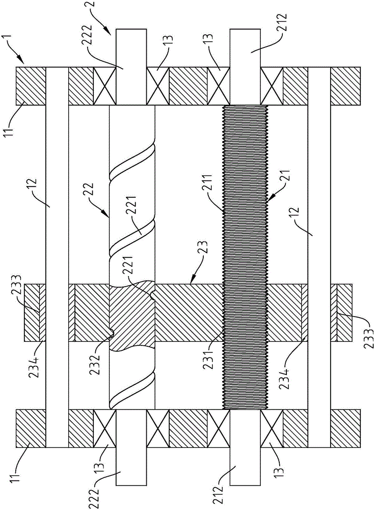
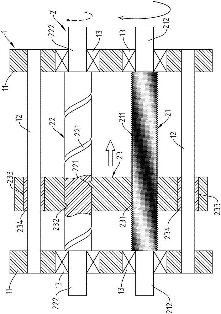
[0012] see figure 1 As shown in the figure, it can be clearly seen from the figure that the present invention is provided with a base 1 and a transmission group 2, wherein:

[0013] The base 1 has two base plates 11 , a plurality of guide rods 12 , and a bearing 13 disposed on the base plate 11 .

[0014] The transmission group 2 has a first transmission shaft 21, a second transmission shaft 22 and a displacement plate 23. The surface of the first transmission shaft 21 is provided with a first external thread 211, and the surface of the second transmission shaft 22 is provided with a second external thread 221. The lead of the second external thread 221 is greater than the lead of the first external thread 211 , the first pivoting portion 212 is provided at both ends of the first transmission shaft 21 , and the second pivoting portion 222 is provided at both ends of the second transmission shaft 22 . The first pivot portion 212 and the second pivot portion 222 are supported a...


PUM


Abstract

The invention provides a speed reducing transmission device. The speed reducing transmission device is provided with a base and a transmission set; the base is provided with guiding rods which are connected to base plates; the transmission set is provided with a first transmission shaft, a second transmission shaft and a displacement plate with penetrating holes connected to the peripheral edges of the guiding rods in a sleeving manner, wherein the first transmission shaft and the second transmission shaft are connected to the base plates in a pivoted manner; the displacement plate is made to move back and forth on the guiding rods in the transverse direction; the surface of the first transmission shaft and the surface of the second transmission shaft are provided with a first external thread and a second external thread correspondingly, and the first external thread and the second external thread are different in screw lead; a first internal thread and a second internal thread are arranged in the displacement plate and are in screw joint with the first external thread and the second external thread correspondingly; the first transmission shaft is made to rotate and drive the displacement plate to move on the guiding rods, so that the displacement of the displacement plate can drive the second transmission shaft to rotate; and the speed is converted by means of the threads, so that the speed reducing transmission device can be simplified, maintenance is convenient, and the using cost is reduced.

Description

technical field [0001] The present invention relates to a deceleration transmission device, in particular to a deceleration transmission device using threads as speed conversion. Background technique [0002] Press, generally used to transmit power and motion in the mechanism, the application range of reducers is quite wide, common reducers are gear reducer (Gear reducer), worm reducer (Worm wheel reducer), planetary gear reducer (Planetary gears) ), etc. These reducers are all gears or gears and worms, which are complex in structure and difficult to maintain, and have a high cost of use. [0003] Therefore, how to solve the above-mentioned existing problems and deficiencies is an urgent research and development issue for the relevant industry. SUMMARY OF THE INVENTION [0004] The main purpose of the present invention is to use the thread to convert the speed, thereby simplifying the deceleration mechanism, facilitating maintenance and reducing the use cost. [0005] In...

Claims


Application Information

Patent Timeline
IPC IPC(8): F16H25/20
CPCF16H37/00F16H25/20
Inventor 简祯祈宋汉钏
Owner NANJING TALIANG TECH CO LTD
Why Eureka
Try Eureka