An anti-icing water conservancy engineering gate

A technology for water conservancy projects and gates, which is applied in the field of anti-icing water conservancy project gates. It can solve the problems of improving utilization efficiency, difficulty in gate power supply, and decline in gate life, so as to reduce utilization and conversion, optimize water flow utilization, and reduce rotation speed. Effect

Active Publication Date: 2018-12-04
ZHEJIANG ZHONGFU FLUID MASCH CO LTD
View PDF6 Cites 0 Cited by
  • Summary
  • Abstract
  • Description
  • Claims
  • Application Information

AI Technical Summary

Problems solved by technology

However, the material of the general gate is alloy or alloy and concrete composite structure. When heated by electric heating components after being cooled, it will affect the stress distribution of the alloy material on the surface of the gate. After many times of alternating cold and heat, the gate will be The surface material has local stress concentration, resulting in local brittleness and cracks, which greatly reduces the life of the gate
However, if the method of maintaining the normal temperature of the gate surface is used to solve the freezing problem, a large amount of electric energy will be consumed, and it is difficult to power the gate, so it is more difficult to realize
[0003] Hydro-gate power generation has been a field of research concentration in recent years, but conventional sluice power generation is either water, wind and / or solar hybrid power generation, or pure hydropower generation, that is, it will inevitably use the kinetic energy of water flow, basically using The blades of the water wheel, while the height of the gate is often changed, the blades of the water wheel cannot keep half of the water surface and half of the water below the water surface at all times, so that the efficiency of the water wheel power generation is low, thus increasing the cost from another angle (using Low efficiency means less output, which reduces the benefit of the same infrastructure, that is, increases the cost)

Method used


Image

  • An anti-icing water conservancy engineering gate
  • An anti-icing water conservancy engineering gate
  • An anti-icing water conservancy engineering gate

Examples


Embodiment 1

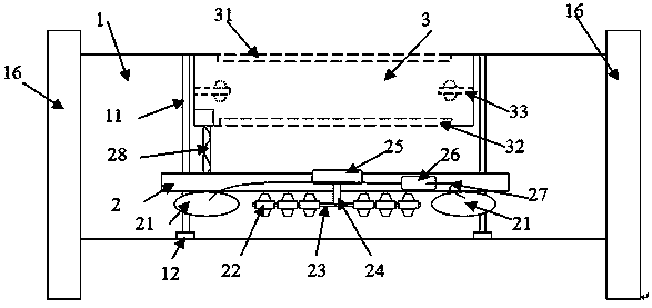
[0029] Such as figure 1 as shown,

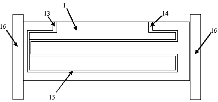
[0030] An anti-icing water conservancy engineering gate comprises a gate plate, a column, a power generation device and a water storage device arranged on the water surface behind the gate plate, and a circulating water pipe arranged on the water surface of the gate plate.

[0031] The column is arranged on both sides of the gate plate, and is used for fixing the gate plate and realizing the rising and falling of the gate plate through the slideway.

[0032] The power generation device is arranged on the backwater surface of the gate, and includes two vertical slide rails, a power generation device bracket, an air bag, water wheel blades, a water wheel shaft, a power conversion shaft, a generator set, an air pump, an inflation pipeline, and a wire channel; The straight slide rails are parallel to the uprights, and are respectively fixed on the two ends of the uprights on the backwater surface of the gate. One end of the fastening slider is...

Embodiment 2

[0047] An anti-icing water conservancy engineering gate comprises a gate plate, a column, a power generation device and a water storage device arranged on the water surface behind the gate plate, and a circulating water pipe arranged on the water surface of the gate plate.

[0048] The column is arranged on both sides of the gate plate, and is used for fixing the gate plate and realizing the rising and falling of the gate plate through the slideway.

[0049] The power generation device is arranged on the backwater surface of the gate, and includes two vertical slide rails, a power generation device bracket, an air bag, water wheel blades, a water wheel shaft, a power conversion shaft, a generator set, an air pump, an inflation pipeline, and a wire channel; The straight slide rails are parallel to the uprights, and are respectively fixed on the two ends of the uprights on the backwater surface of the gate. One end of the fastening slider is fixed on the power generation device ...

Embodiment 3

[0060] An anti-icing water conservancy engineering gate comprises a gate plate, a column, a power generation device and a water storage device arranged on the water surface behind the gate plate, and a circulating water pipe arranged on the water surface of the gate plate.

[0061] The column is arranged on both sides of the gate plate, and is used for fixing the gate plate and realizing the rising and falling of the gate plate through the slideway.

[0062] The power generation device is arranged on the backwater surface of the gate, and includes two vertical slide rails, a power generation device bracket, an air bag, water wheel blades, a water wheel shaft, a power conversion shaft, a generator set, an air pump, an inflation pipeline, and a wire channel; The straight slide rails are parallel to the uprights, and are respectively fixed on the two ends of the uprights on the backwater surface of the gate. One end of the fastening slider is fixed on the power generation device ...


PUM


Abstract

The invention relates to an anti-icing hydraulic engineering gate. The anti-icing hydraulic engineering gate comprises a gate plate, a stand column, a power generation device arranged on a water opposing surface of the gate plate, a water storage device, and a circulating water pipe arranged on a water facing surface of the gate plate. Through improvement of all parts, the hydraulic gate realizes autonomous ice removal under the condition of basically needing no external energy, and can realize remote intelligent control.

Description

technical field [0001] The invention belongs to the field of water conservancy engineering equipment, and in particular relates to an anti-icing water conservancy engineering gate. Background technique [0002] The most conventional component in large-scale water conservancy projects is the gate. Generally, multiple water conservancy gates in large-scale water conservancy projects are arranged side by side, and are controlled simultaneously or separately to realize the control of water flow. However, when the temperature is low, a large amount of ice will form on the upper part of the water conservancy gate, which not only greatly increases the weight of the gate, but also seriously affects the up and down movement of the gate. In the prior art, there are also some researches on the deicing of the gate, but basically, electric heating wires or other electric heating components are arranged on the surface of the gate to perform the ice melting operation. However, the materia...

Claims


Application Information

Patent Timeline
Patent Type & Authority Patents(China)
IPC IPC(8): E02B7/28F03B13/00F03B3/12F03B11/00
CPCE02B7/28F03B3/121F03B11/00F03B13/00Y02E10/20
Inventor 郭策王猛
Owner ZHEJIANG ZHONGFU FLUID MASCH CO LTD
Why Eureka
Try Eureka