Rigid endoscope air drying device for ENT

An ENT, air-drying device technology, applied to endoscopes, drying gas arrangements, non-progressive dryers, etc., can solve problems such as affecting drying efficiency and being unable to be directly blown, achieving improved effects and increased friction force effect

Active Publication Date: 2022-05-17
烟台拉斐尔生物科技有限公司
View PDF5 Cites 0 Cited by
  • Summary
  • Abstract
  • Description
  • Claims
  • Application Information

AI Technical Summary

Problems solved by technology

[0005] The object of the present invention is to provide a rigid endoscope air-drying device for otolaryngology, to solve the problem in the prior art that the endoscope is inserted into the first through hole of the placement plate for fixing, and then blows and dries through the nozzle, but the internal Sight glass principle The surface of the outer wall at one end of the nozzle cannot be directly blown, which will affect the technical problem of its drying efficiency

Method used


Image

  • Rigid endoscope air drying device for ENT
  • Rigid endoscope air drying device for ENT
  • Rigid endoscope air drying device for ENT

Examples


Embodiment 1

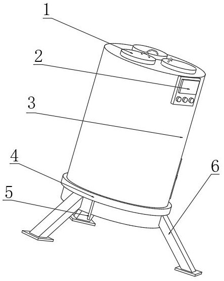
[0037] Combine below Figure 1 to Figure 7 As shown, the embodiment of the present invention provides a rigid endoscope air-drying device for otolaryngology, including a drying housing 3, a partition 11 is installed at the bottom of the inner wall of the drying housing 3, and the outer wall of the top of the partition 11 is rotatably connected with a Hollow pipe 15, the outer wall of one side of hollow pipe 15 is equipped with the first air nozzle of equidistant distribution, and the bottom of outer wall of one side of hollow pipe 15 is equipped with the second air nozzle, and the top of outer wall of one side of hollow pipe 15 is equipped with air nozzle 20, separates The top outer wall of the plate 11 is connected with threaded rods 19 distributed equidistantly through thread rotation, and the outer wall of the threaded rod 19 is connected with a Z-shaped fixed plate 22 through threaded rotation, and one side of the top outer wall of the Z-shaped fixed plate 22 is connected w...

Embodiment 2

[0048] Based on the air-drying device for rigid endoscope used in ENT department provided in the first embodiment of the present application, the second embodiment of the present application proposes another air-dried device for rigid endoscope used in department of ENT department. The second embodiment is only a preferred mode of the first embodiment, and the implementation of the second embodiment will not affect the independent implementation of the first embodiment.

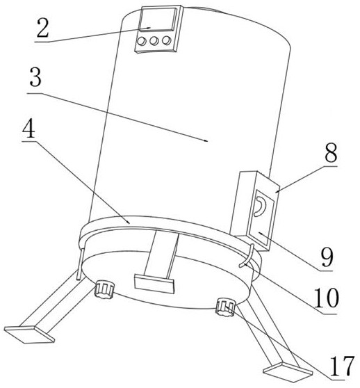
[0049] Attached below Figure 8 And the implementation mode The second embodiment of the invention is further described, the bottom of the inner wall of the drying housing 3 is hinged with an electric push rod 33, and the other end of the electric push rod 33 is hinged with the corresponding outer wall of the outlet pipe 10 side, so that When the PLC controller 2 detects that the motor 17 is turned on, the PLC controller 2 controls the electric push rod 33 to shrink, so that the air jet bucket on the air outl...


PUM


Abstract

The invention discloses a rigid endoscope air-drying device for otolaryngology, relates to the technical field of air-drying devices, and comprises a drying shell. A partition is installed at the bottom of the inner wall of the drying shell, and the outer wall of the top of the partition is connected with a hollow through a bearing. The outer wall of one side of the hollow tube is equipped with first air nozzles distributed equidistantly, and the bottom of the outer wall of one side of the hollow tube is installed with second air nozzles. The invention is provided with an air pump, the air outlet pipe on the air pump can drive the arc-shaped plate and the hollow tube to rotate, and the driving gear on the hollow tube drives the polygonal cylinder on the driven gear to rotate, thereby driving the fixed endoscope to rotate. Fully air-dry the surface of the endoscope. The trapezoidal groove on the outer wall of the protective tube can allow the wind to enter the inside of the protective tube, reducing the splash of water droplets on the outer wall of the protective tube to the outside, thereby avoiding affecting the normal air-drying of other endoscopes.

Description

technical field [0001] The invention relates to the technical field of air-drying devices, in particular to a rigid endoscope air-drying device for ENT. Background technique [0002] Rigid endoscopes include nasal endoscopes, ear endoscopes, rhinoscopes, and indirect laryngoscopes. In view of the large number of patients in the ENT clinic and the frequent use of endoscopes, at present, after the endoscope is disinfected, the surface moisture is generally dried manually with a cloth, which may cause secondary pollution and reduce the effect of disinfection , and easily damaged. [0003] Publication No. CN108398007A Chinese invention patent discloses a rigid endoscope air-drying device for otolaryngology. The patent includes a mounting frame, an air-drying box, a first sealing ring, a first bearing seat, a hollow rotating tube, and a first rotating rod. , handle, first slide rail, first slider, fixed block, etc.; placing board and box door, an air-drying box is set on the up...

Claims


Application Information

Patent Timeline
Patent Type & Authority Patents(China)
IPC IPC(8): F26B11/18F26B21/00F26B25/02F26B25/18A61B1/00
CPCF26B11/18F26B21/001F26B21/004F26B25/02F26B25/18A61B1/00195
Inventor 姜海华景怀香姚小燕林明霞
Owner 烟台拉斐尔生物科技有限公司
Why Eureka
Try Eureka