
Combustion chamber of liquid fuel boiler

A liquid fuel and combustion chamber technology, which is applied in the directions of liquid fuel supply/distribution, combustion method, etc., can solve the problems of insufficient combustion of fuel, inability to monitor the internal state of the combustion chamber in real time, and poor monitoring of the combustion chamber system. achieve the effect of preventing detonation

Inactive Publication Date: 2017-03-29
HARBIN JINJING BOILER
View PDF10 Cites 0 Cited by
  • Summary
  • Abstract
  • Description
  • Claims
  • Application Information

AI Technical Summary

Problems solved by technology

[0004] At present, in boilers used with liquid fuel, there is no good monitoring system for the combustion chamber, and the internal state of the combustion chamber cannot be well monitored in real time. The addition of liquid fuel is also used in injection combustion, which cannot fully burn the fuel and make full use of the fuel. Efficient combustion rate

Method used


Image

  • Combustion chamber of liquid fuel boiler
  • Combustion chamber of liquid fuel boiler

Examples


Embodiment 1

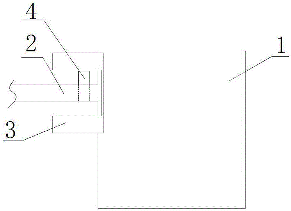
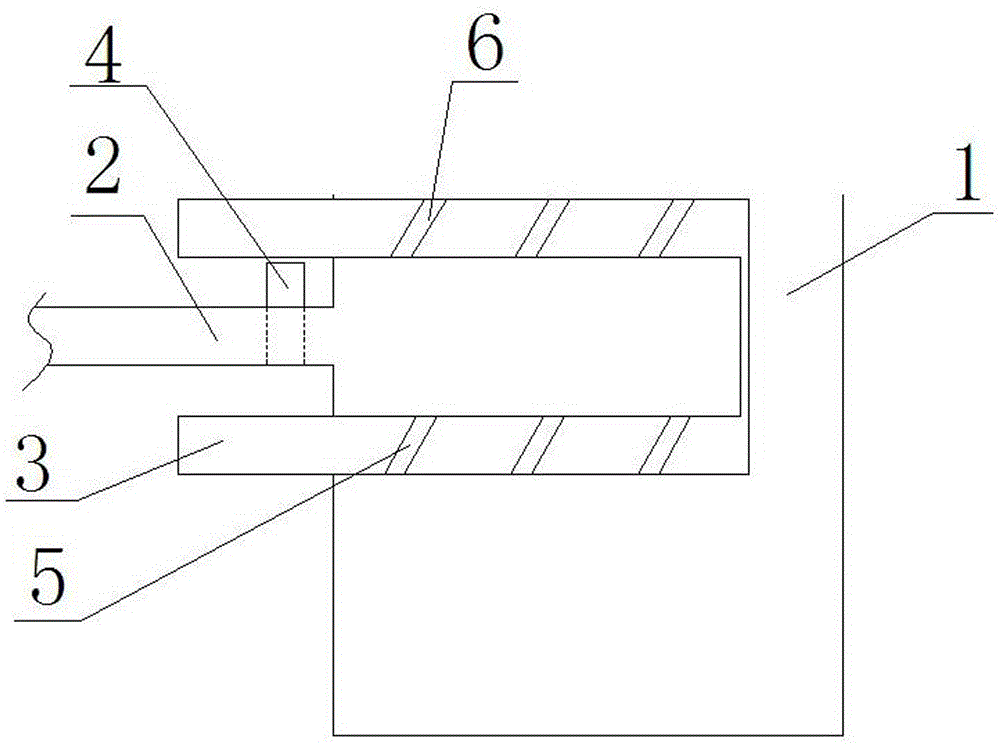
[0017] A combustion chamber of a liquid fuel boiler, comprising a combustion chamber 1; characterized in that: the upper part of the side wall of the combustion chamber 1 is provided with a plurality of liquid fuel feed pipes 2; A U-shaped telescopic fuel filling box 3 is provided. The U-shaped telescopic fuel filling box 3 includes an upper telescopic plate, a lower telescopic plate and a side plate; the upper telescopic plate and the lower telescopic plate are respectively connected to the liquid fuel feed pipe 2 Above and below the side plate; the top of the side plate is connected with the upper telescopic plate, and the bottom is connected with the lower telescopic plate; the upper telescopic plate is provided with a plurality of vent holes 6; the lower telescopic plate is provided with a plurality of leakage guide ports .

[0018] The liquid fuel feed pipe 2 is provided with an on-off valve 4.

[0019] Both the vent hole 6 and the leakage guide port 5 are provided with on...

Embodiment 2

[0021] The working principle of the present invention:

[0022] In the present invention, when adding liquid fuel to the inside of the combustion chamber 1, in order to prevent deflagration caused by adding liquid fuel when the furnace is not shut down or to prevent burning of the liquid fuel feed pipe 2, a U-shaped telescopic type is added Fuel filling box 3; the telescopic fuel filling box 3 is opened into the combustion chamber 1 when in use, the liquid fuel feed pipe 2 sends the liquid fuel to the telescopic fuel filling box 3, and then the liquid fuel feed pipe is closed After closing the valve on 2, open the vent 6 on the upper telescopic plate of the telescopic fuel filling box 3, and then open the leakage guide port 5 on the lower telescopic plate of the telescopic fuel filling box 3 to make the telescopic The liquid fuel inside the fuel filling box 3 flows into the combustion chamber 1, and the liquid fuel is added safely and effectively, so that no deflagration occurs...


PUM


Abstract

The invention discloses a combustion chamber of a liquid fuel boiler. The combustion chamber of the liquid fuel boiler comprises the combustion chamber, and is characterized in that a plurality of liquid fuel feeding pipes are arranged on the upper part of the side wall of the combustion chamber; U-shaped telescopic fuel filling boxes are arranged corresponding to the liquid fuel feeding pipes, and comprise upper telescopic plates, lower telescopic plates and side plates; the upper telescopic plates and the lower telescopic plates are arranged above and under the liquid fuel feeding pipes; the upper telescopic plates are connected to the top parts of the side plates; the lower telescopic plates are connected to the bottom parts of the side plates; a plurality of vent holes are formed in the upper telescopic plates; a plurality of liquid leakage guiding ports are formed in the lower telescopic plates; switch valves are arranged on the liquid fuel feeding pipes; and open-close valves are arranged in the vent holes and the liquid leakage guiding ports. The combustion chamber of the liquid fuel boiler provided by the invention has the advantages that liquid fuels can be safely added, the phenomenon of detonation or burnout of the liquid fuel feeding pipes occurred when the liquid fuels are added in the combustion chamber is effectively prevented, and the like.

Description

Technical field [0001] The invention relates to a Internal combustion chamber of boiler , In particular, it relates to a combustion chamber of a liquid fuel boiler. Background technique [0002] The boiler is a kind of energy conversion equipment. The energy input to the boiler includes chemical energy and electric energy in the fuel, and the boiler outputs steam, high temperature water or organic heat carrier with certain thermal energy. The original meaning of pot refers to a water container heated on a fire, and a furnace refers to a place where fuel is burned. A boiler includes two parts: a pot and a furnace. The hot water or steam produced in the boiler can directly provide the required thermal energy for industrial production and people's lives, and can also be converted into mechanical energy by a steam power device, or converted into electrical energy by a generator. Boilers that provide hot water are called hot water boilers, which are mainly used in daily life, but ...

Claims


Application Information

Patent Timeline
Patent Type & Authority Applications(China)
IPC IPC(8): F23K5/02F23K5/14
Inventor 谷哲学
Owner HARBIN JINJING BOILER
Learn More