Supercharge Your Innovation With Domain-Expert AI Agents!

Solar photovoltaic panel applied to roof

A solar photovoltaic panel and photovoltaic panel technology, applied in the field of solar photovoltaic panels, can solve the problems of photovoltaic panel bracket damage, erosion, inconvenient maintenance, etc., and achieve the effects of extending service life, reducing contact, and facilitating maintenance and inspection work.

Inactive Publication Date: 2017-03-29
DONGGUAN TIANHE ELECTROMECHANICAL DEV CO LTD
View PDF5 Cites 0 Cited by
  • Summary
  • Abstract
  • Description
  • Claims
  • Application Information

AI Technical Summary

Problems solved by technology

[0004] At present, due to the influence of the photovoltaic environment, large-scale photovoltaic power station projects have grown rapidly in the past two years. The current situation of my country's large population and small land forces many photovoltaic power stations to develop on the roof of large factories, but installing photovoltaic panels on the roof of the factory The ground is different. Installing photovoltaic panels on the roof of the factory building will be eroded by wind and rain. The rainwater falling on the roof of the factory building will flow down the roof and pass through the photovoltaic panel brackets installed on the roof. The photovoltaic panel brackets are prone to rust due to long-term contact with rainwater. Causes damage to the photovoltaic panel support, and is not easy to repair

Method used


Image

  • Solar photovoltaic panel applied to roof
  • Solar photovoltaic panel applied to roof

Examples


Embodiment Construction

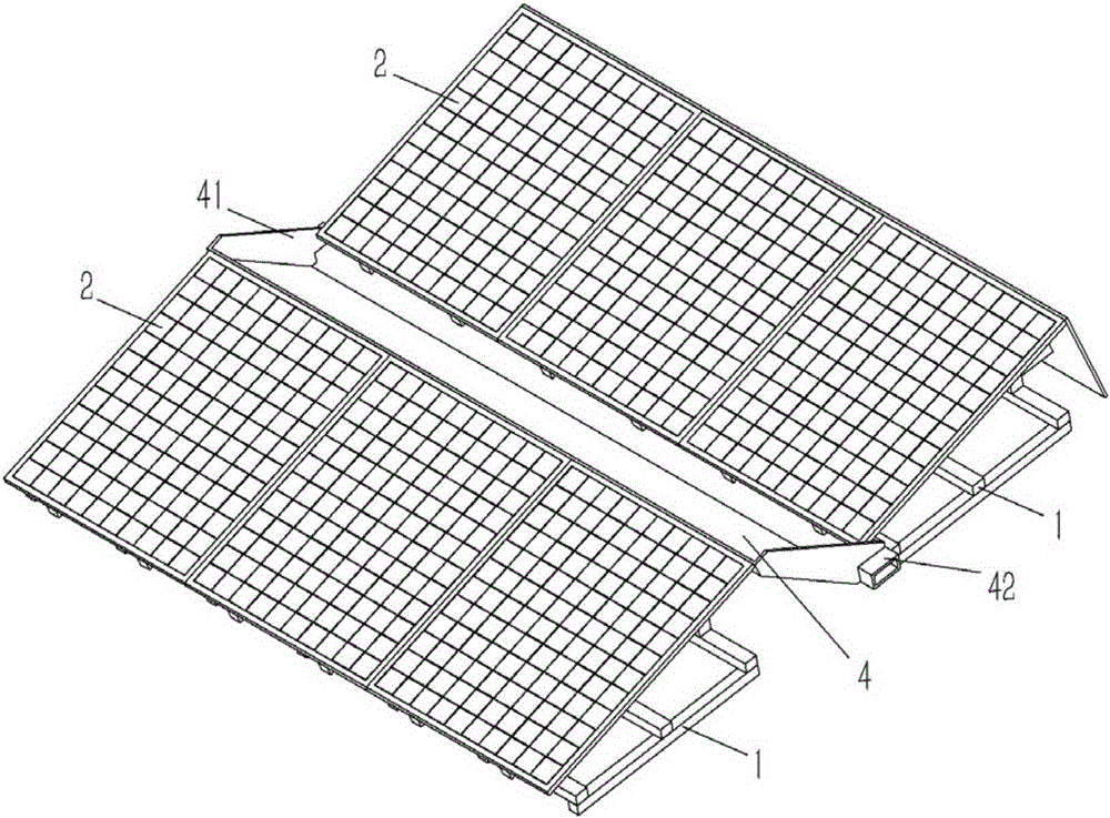
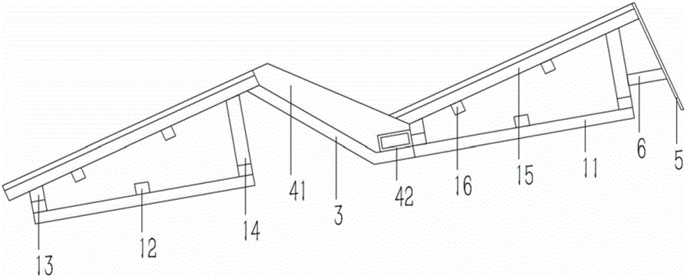
[0019] Example: see figure 1 , 2 As shown, a solar photovoltaic panel applied to the roof includes a plurality of photovoltaic panel brackets 1, and the photovoltaic panel bracket 1 is fixed with an inclined photovoltaic panel 2. The photovoltaic panel brackets 1 are fixed on the roof in a plurality of rows. The board support 1 is composed of a longitudinal bottom rod 11, a cross rod 12, a front support rod 13, a rear support rod 14 and a C-shaped channel steel 15. A number of supports are installed between the photovoltaic panel supports 1 between two adjacent rows. Rod 3, the upper end of the supporting rod 3 is fixed on the C-shaped channel steel 15 of the previous row of photovoltaic panel support 1, and the lower end of the supporting rod 3 is formed with a folding rod, and the folding rod is fixed on the cross bar 12 of the next row of photovoltaic panel support 1 On; the supporting rod 3 is fixed with a water tank 4, the upper side of the water tank 4 is fixed on the phot...


PUM


Abstract

The invention discloses a solar photovoltaic panel applied to a roof. Obliquely-arranged photovoltaic panel bodies are fixed to photovoltaic panel brackets of the solar photovoltaic panel. The multiple rows of photovoltaic panel brackets are fixed to the roof. Each photovoltaic panel bracket is composed of a longitudinal bottom rod, a cross rod, a front supporting rod, a back supporting rod and C-shaped U-steel. The upper end of a bearing rod is fixed to the C-shaped U-steel of the previous row of photovoltaic panel bracket, and a folding rod is formed at the lower end of the bearing rod. The folding rod is fixed to the cross rod of the next row of photovoltaic panel bracket. A water receiving tank is fixed to the bearing rod. The upper side edge of the water receiving tank is fixed to the photovoltaic panel body of the previous row of photovoltaic panel bracket. The lower side edge of the water receiving tank is fixed to the front supporting rod of the next row of photovoltaic panel bracket. Baffles are formed at the lower side edge, the left side edge and the right side edge of the water receiving tank. Water draining tank openings are formed in the baffles at the left side edge and the right side edge of the water receiving tank. An obliquely-arranged rain sheltering plate is fixed to the last row of photovoltaic panel bracket on the roof. According to the solar photovoltaic panel applied to the roof, the contact between the photovoltaic panel brackets and rain water can be reduced, and the rusting condition of the photovoltaic panel brackets can be relieved.

Description

[0001] Technical field: [0002] The present invention relates to the technical field of solar panels, and more specifically to a solar photovoltaic panel applied to the roof. [0003] Background technique: [0004] At present, under the influence of the photovoltaic environment, large-scale photovoltaic power station projects have been growing rapidly in the past two years. The current situation of China's large population and small land has forced many photovoltaic power stations to develop on the roof of large-scale factory buildings. However, the installation of photovoltaic panels on the roof of the factory Different on the ground, the installation of photovoltaic panels on the roof of the factory will be eroded by wind and rain. The rainwater falling on the roof of the factory will flow down the roof and pass through the photovoltaic panel bracket installed on the roof. The photovoltaic panel bracket is prone to rust when exposed to rain for a long time. This leads to the destr...

Claims


Application Information

Patent Timeline
IPC IPC(8): F24J2/52H02S20/23
CPCF24S25/20F24S2025/01H02S20/23Y02B10/10Y02B10/20Y02E10/47Y02E10/50
Inventor 赵鸿斌
Owner DONGGUAN TIANHE ELECTROMECHANICAL DEV CO LTD
Features
  • R&D
  • Intellectual Property
  • Life Sciences
  • Materials
  • Tech Scout
  • Unparalleled Data Quality
  • Higher Quality Content
  • 60% Fewer Hallucinations
Learn More