Handle holding and knocking machine

A prosthesis handle and fixed rod technology, which is applied in the fields of medical science, hip joint, prosthesis, etc., can solve the problems of difficulty in removing instruments from the prosthesis handle, time-consuming and affecting surgical operations.

Active Publication Date: 2017-04-05
BEIJING NATON TECH GRP CO LTD
View PDF6 Cites 0 Cited by
  • Summary
  • Abstract
  • Description
  • Claims
  • Application Information

AI Technical Summary

Problems solved by technology

The common prosthetic stem implanters of various companies in the market use a threaded structure to realize the integration of the prosthetic stem and the instrument. At the same time, there is a U-shaped anti-rotation groove structure to realize the adjustment of the anteversion angle during the operation. This structure has the following disadvantages: ( 1) When the prosthesis stem is installed, it needs to be connected with the prosthesis stem by rotating the threaded rod of the instrument. After the prosthesis stem is implanted in place, the connection must be released by rotating the threaded rod again. This operation is time-consuming; (2) knocking When hitting the prosthesis handle, there is a gap in the threaded connection (even if the thread processing accuracy is improved), resulting in damage to the thread in the prosthesis handle. This situation often occurs in clinical practice where it is difficult to remove the instrument from the prosthesis handle, which affects surgical operations and Wastes time and increases the risk of infection for the patient
At the same time, the more serious situation is that when the patient undergoes revision surgery in the future, it will bring difficulty in taking the prosthetic stem.
In addition, there are many specifications and types of prosthetic handles on the market. When designing and developing different handles according to different surgical needs, usually according to the structural characteristics of specific handles, special matching instruments are designed. Manufacturers may develop handles with different structural specifications, which will result in a wide variety of supporting equipment, increase inventory, and increase production costs. If different types of prosthetic handles can be designed for holding and percussion implantation equipment has great practical significance

Method used


Image

  • Handle holding and knocking machine
  • Handle holding and knocking machine
  • Handle holding and knocking machine

Examples


Embodiment Construction

[0023] Typical embodiments embodying the features and advantages of the present invention will be described in detail in the following description. It should be understood that the present invention is capable of various changes in different embodiments without departing from the scope of the present invention, and that the description and drawings therein are illustrative in nature and not limiting. this invention.

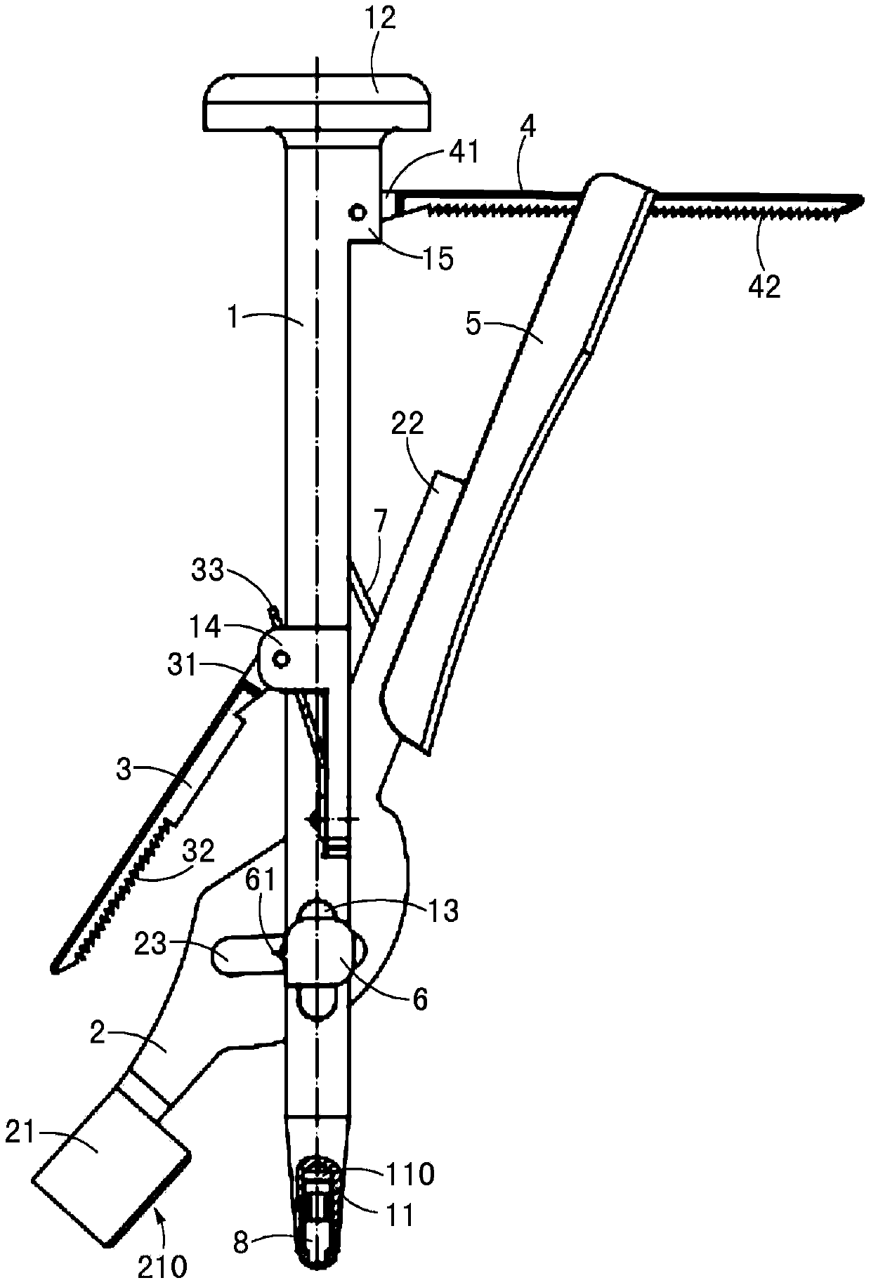
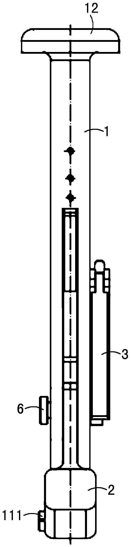
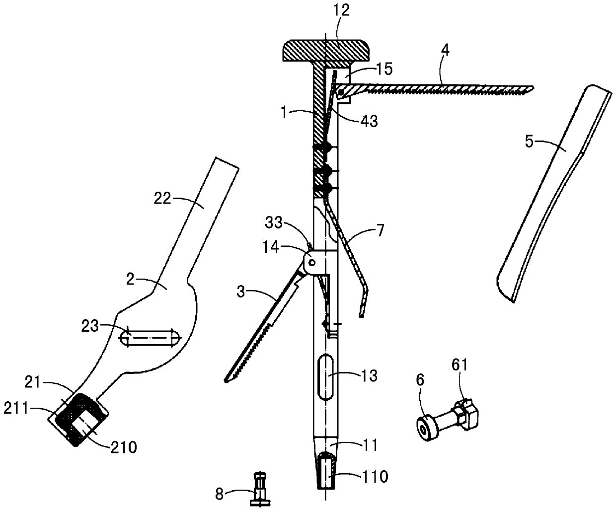
[0024] figure 1 and figure 2 A structural diagram of an embodiment of the handle handle of the present invention is shown, as figure 1 and figure 2 As shown, this embodiment includes a fixed rod 1 and a rotating rod 2 . Wherein, the fixed rod 1 includes an operating end 12 and a clamping end 11, and the clamping end 11 is provided with an engagement hole 110, for reference Figure 4 shown. The rotating rod 2 is rotatably connected to the movable rod 1, including an operating end 22 and a clamping end 21, and the clamping end 21 is provided with a slotted ...


PUM


Abstract

The invention discloses a handle holding and knocking machine applied to operating a prosthesis handle. The prosthesis handle comprises a cone head and an operating hole. The handle holding and knocking machine comprises a fixed rod and a rotating rod; one end of the fixed rod is connected with the operating hole; the rotating rod can be rotationally connected with the fixed rod, and one end of the rotating rod is provided with a groove hole buckled with the cone head. In the handle holding and knocking machine, the fixed rod is connected with the operating hole, the rotating rod is buckled with the cone head, the rotating rod is rotationally connected with the fixed rod, a triangle is formed between the connecting structures, by operating the fixed rod and the rotating rod in cooperation, the prosthesis handle is clamped or released, and clamping and knocking implantation of the prosthesis handle are achieved.

Description

technical field [0001] The invention relates to an instrument for artificial hip joint total hip and half hip replacement surgery. Background technique [0002] Currently, in artificial hip replacement surgery, one of the most commonly used instruments is the prosthetic stem implanter. The common prosthetic stem implanters of various companies in the market use a threaded structure to realize the integration of the prosthetic stem and the instrument. At the same time, there is a U-shaped anti-rotation groove structure to realize the adjustment of the anteversion angle during the operation. This structure has the following disadvantages: ( 1) When the prosthesis stem is installed, it needs to be connected with the prosthesis stem by rotating the threaded rod of the instrument. After the prosthesis stem is implanted in place, the connection must be released by rotating the threaded rod again. This operation is time-consuming; (2) knocking When hitting the prosthesis handle, t...

Claims


Application Information

Patent Timeline
Patent Type & Authority Applications(China)
IPC IPC(8): A61F2/46
CPCA61F2/4603A61F2/4607
Inventor 张旭东董骧
Owner BEIJING NATON TECH GRP CO LTD
Why Eureka
Try Eureka