Corner stirring type screw conveying mechanism with cleaning structure

A technology of screw conveying and turning angle, which is applied in the direction of conveyor objects, cleaning devices, transportation and packaging, etc. It can solve the problems of affecting work efficiency, easy material jamming at corners, and troublesome operation, so as to improve cleaning efficiency, speed up material transportation, and improve The effect of delivery efficiency

Inactive Publication Date: 2017-04-05
M & J MACHINERY ENGINEER
View PDF5 Cites 0 Cited by
  • Summary
  • Abstract
  • Description
  • Claims
  • Application Information

AI Technical Summary

Problems solved by technology

The existing ordinary screw conveyor is easy to jam the material at the corner during the conveying process, which may easily cause the motor to burn out, or damage the parts, and a

Method used


Image

  • Corner stirring type screw conveying mechanism with cleaning structure

Examples


Example Embodiment

[0009] The specific embodiments of the present invention will be further described below in conjunction with the accompanying drawings.

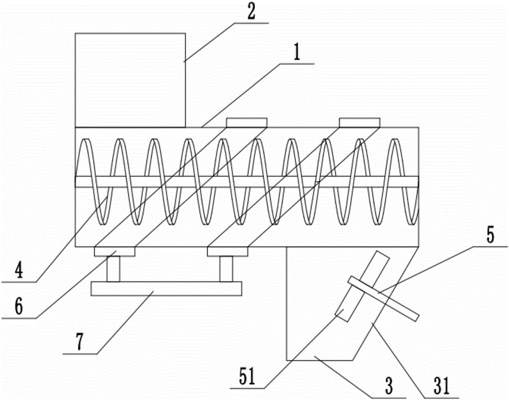
[0010] Such as figure 1 As shown, the corner stirring type spiral conveying mechanism with cleaning structure of this embodiment includes a conveying pipe 1. The upper side of one end of the conveying pipe 1 is connected to the feed pipe 2, and the lower side of the other end is connected to the discharge pipe 3 and the conveying pipe 1. A screw conveyor 4 is installed in the center, the side of the discharge pipe 3 away from the feed pipe 2 has an inclined installation surface 30 close to the center of the pipe, and the inclined installation surface 30 is installed with a stirrer 5 and the stirrer 5 The blade 51 is placed in the discharge pipe 3, and the stirring blade 51 is a flat plate structure; the outer wall of the conveying pipe 1 is equipped with a cleaning ring 6 spaced apart along its axial direction. The cleaning ring 6 has an annula...


PUM


Abstract

The invention relates to a corner stirring type screw conveying mechanism with a cleaning structure. The corner stirring type screw conveying mechanism comprises a conveying pipe. The upper side of one end of the conveying pipe communicates with a feeding pipe, and the lower side of the other end of the conveying pipe communicates with a discharging pipe. A screw conveyor is mounted in the conveying pipe. The side, away from the feeding pipe, of the discharging pipe is provided with an inclined mounting face close to the center of the discharging pipe. A stirrer is mounted on the inclined mounting face. Stirring blades of the stirrer are arranged in the discharging pipe and are each of a flat-plate-shaped structure. The outer wall of the conveying pipe is provided with cleaning rings arranged at intervals in the axial direction of the conveying pipe. Each cleaning ring is provided with an annular cleaning cavity. Through holes communicating with one another are formed in the inner walls of the cleaning rings and the inner wall of the conveying pipe. The cleaning rings are connected with a cleaning pipe. The cleaning pipe is connected with a cleaning pump. According to the corner stirring type screw conveying mechanism with the cleaning structure, the stirrer is arranged in the discharging pipe, conveying of materials at discharging corners is accelerated, the corners are prevented from being stuck by the materials, and the conveying efficiency is improved.

Description

technical field [0001] The invention relates to the field of packaging machinery, in particular to a conveying mechanism. Background technique [0002] In the prior art, on the filling production line, it is usually necessary to displace the powdery material, which is generally completed by a screw conveyor. The existing ordinary screw conveyor is easy to jam the material at the corner during the conveying process, which is easy to cause the motor to burn out, or damage the parts, and affect the work efficiency. When the existing common screw conveyor needs to be cleaned, the whole casing must be disassembled for cleaning, and the operation is rather cumbersome. Contents of the invention [0003] In view of the above-mentioned problems existing in the prior art, the applicant conducted research and improvement to provide a corner-stirring screw conveying mechanism with a cleaning structure, and adopted the following technical solutions: [0004] A corner stirring screw c...

Claims


Application Information

Patent Timeline
IPC IPC(8): B65G33/24B65G45/22
CPCB65G33/24B65G45/22
Inventor 何海英
Owner M & J MACHINERY ENGINEER
Why Eureka
Try Eureka