High-efficiency ore crushing and sorting device

A kind of ore crushing and sorting device technology, which is applied in the direction of grain processing, etc., can solve the problems of rigid separation structure, low sorting efficiency, low crushing efficiency, etc., and achieve high crushing efficiency, high sorting efficiency and good effect

Inactive Publication Date: 2017-11-24
南宁众创空间科技有限公司
0 Cites 6 Cited by

AI-Extracted Technical Summary

Problems solved by technology

[0003] However, the current traditional ore crushing and separation structure is rigid, the crushing effi...

Abstract

The invention discloses a high-efficiency ore crushing and sorting device, which includes a shell; the bottom of the shell is symmetrically provided with supporting feet, the left side of the top of the shell is provided with a feeding hopper, and the inner top of the shell corresponds to the lower part of the feeding hopper A primary crushing mechanism is provided, and a secondary crushing mechanism is provided on the lower right side of the primary crushing mechanism. The plate and the lower cavity of the housing form a sorting chamber. The invention provides a high-efficiency ore crushing and sorting device. The invention cleverly sets the primary crushing mechanism and the secondary crushing mechanism, which can avoid material jamming, and the crushing efficiency is high and the effect is good. In addition The invention utilizes the principle that magnetorheological fluid produces rheological phenomena under the action of a magnetic field to cleverly set up a magnetic separation mechanism, which has faster recognition speed, higher separation accuracy, and high separation efficiency. down to work.

Application Domain

Grain treatments

Technology Topic

EngineeringMagnetorheological fluid

Image

  • High-efficiency ore crushing and sorting device
  • High-efficiency ore crushing and sorting device
  • High-efficiency ore crushing and sorting device

Examples

  • Experimental program(1)

Example Embodiment

[0018] The technical solutions in the embodiments of the present invention will be clearly and completely described below in conjunction with the accompanying drawings in the embodiments of the present invention. Obviously, the described embodiments are only a part of the embodiments of the present invention, rather than all the embodiments. Based on the embodiments of the present invention, all other embodiments obtained by those of ordinary skill in the art without creative work shall fall within the protection scope of the present invention.
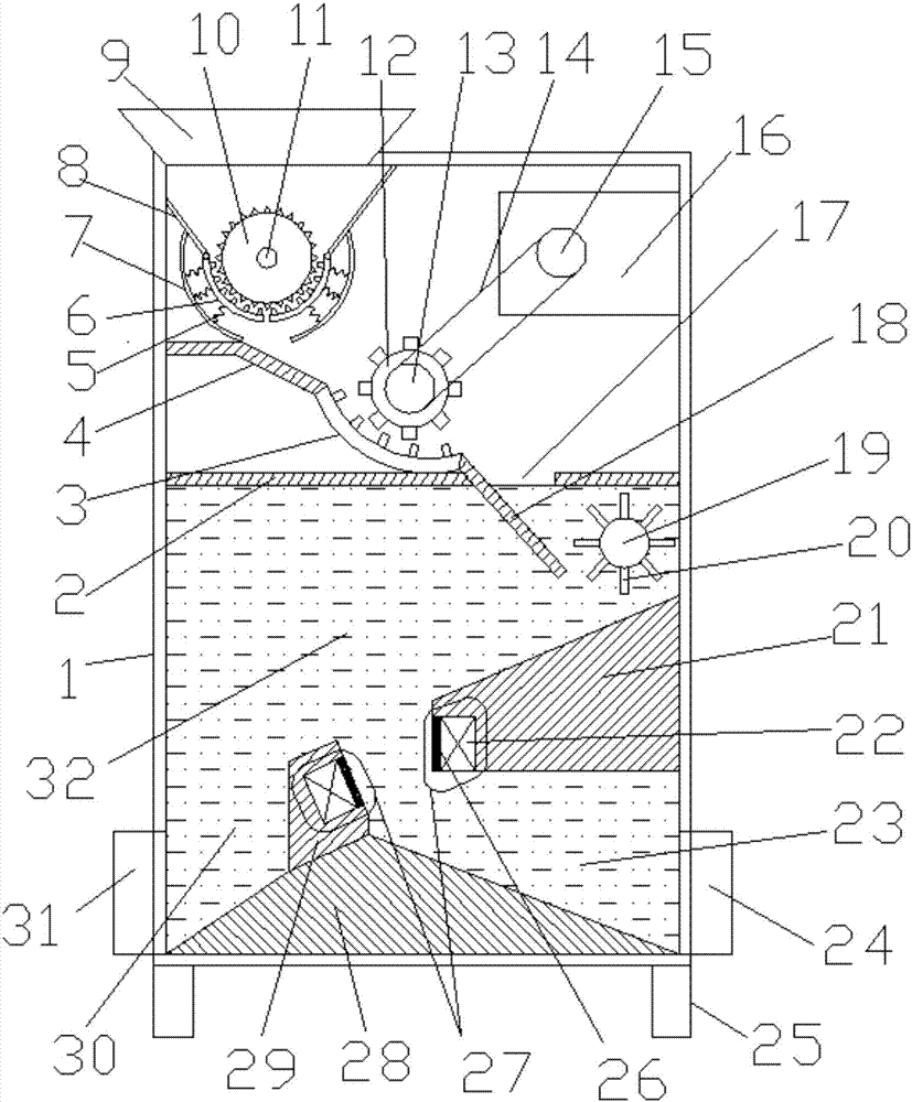
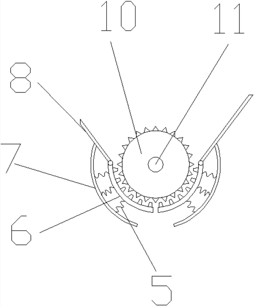
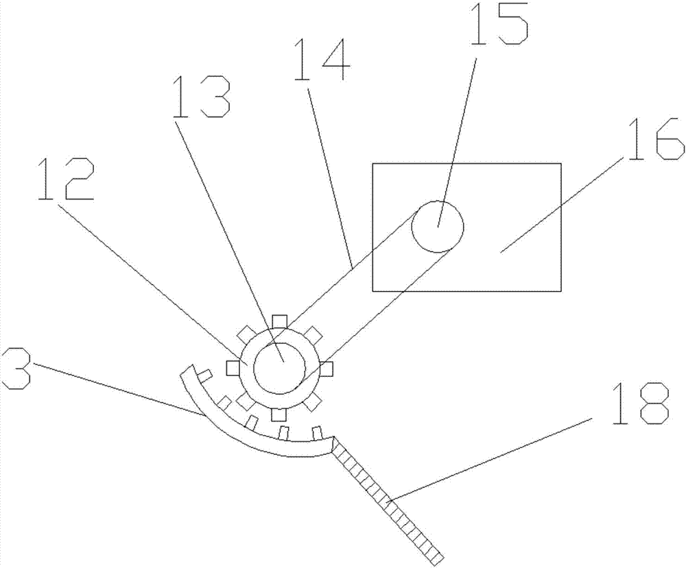
[0019] See Figure 1~3 In the embodiment of the present invention, a high-efficiency ore crushing and sorting device includes a casing 1, and the bottom of the casing 1 is provided with support feet 25 symmetrically, and a hopper 9 is provided on the left side of the top of the casing 1. A preliminary crushing mechanism is provided at the top of the housing 1 corresponding to the lower part of the hopper 9, and a secondary crushing mechanism is provided at the lower right of the preliminary crushing mechanism. The preliminary crushing mechanism and the secondary crushing mechanism are connected through the first deflector 4, A partition 2 is provided on the lower side of the crushing mechanism. The partition 2 and the lower cavity of the housing 1 form a sorting cavity. The right side of the partition 2 is provided with a sorting feed inlet 17, and the secondary crushing mechanism passes through the second diversion The plate 18 passes through the sorting inlet 17 to communicate with the top of the right side of the sorting chamber. The sorting chamber is provided with a first wedge 21 and a second wedge 29, and a first wedge 21 and a second wedge from right to left. 19 is inclined to the lower left, the upper slope of the first wedge 21 and the second wedge 19 are parallel, and a distance is provided between the first wedge 21 and the second wedge 29; the first wedge 21 is fixed on the housing 1 On the right side wall, the bottom of the second wedge 29 is provided with a support block 28, the top ends of the first wedge 21 and the second wedge 29 are embedded with permanent magnet blocks 22, and the sorting cavity is filled with Magnetorheological fluid 32; a first sorting channel 23 to the right is formed between the first wedge 21 and the second wedge 29 and the support block 28, and the right side of the housing 1 corresponds to the bottom end of the first sorting channel 23 A first discharge port 24 is provided; the second wedge 29 and the supporting block 28 form a rightward second sorting channel 30 with the left side wall of the housing 1, and the left side of the housing 1 corresponds to the second sorting channel The bottom end of 30 is provided with a second discharge port 31. The roller shafts 11 at both ends of the first crushing roller 10 are sleeved on bearings provided on the side wall of the housing 1, and are driven by a first motor provided on the outside of the housing 1. A driven pulley 13 is sleeved on the roller shaft of the second crushing roller 12, and a driven pulley 15 on the top right side of the housing 1 is driven by a second motor 16, and the driven pulley 13 It is connected to the driving pulley 15 through a belt 14 in transmission.
[0020] The preliminary crushing mechanism includes two supporting plates 8. The top ends of the two supporting plates 8 are respectively fixed on the inner walls of the housing 1 on the left and right sides of the bottom end of the feeding hopper 9, and the two supporting plates 8 are inclined to the middle to form the same structure as the feeding hopper 9. In the structure of a connected cone-shaped flow deflector, the bottom ends of the two supporting plates 8 are provided with first arc-shaped tooth grooves 6 symmetrically, and a first crushing roller 10 is provided between the two first arc-shaped tooth grooves 6; The outer circumference of the first crushing roller 10 is uniformly provided with crushing teeth meshing with the first arc-shaped tooth grooves 6.
[0021] The top end of the first arc-shaped tooth groove 6 is hingedly connected with the bottom end of the support plate 8, a gap is provided between the bottom ends of the two first arc-shaped tooth grooves 6, and a supporting plate is provided on the lower side of the first arc-shaped tooth groove 6 3. The supporting plate 3 is in an arc shape, the top end of the supporting plate 3 is fixed on the supporting plate 8, and a plurality of compression springs 5 ​​are arranged between the supporting plate 3 and the first arc-shaped tooth groove 6.
[0022] The secondary pulverization mechanism includes a second arc-shaped tooth slot 3, the second arc-shaped tooth slot 3 is inclined downward to the right, and the second arc-shaped tooth slot 3 is fixedly arranged on the first deflector 4 and the second deflector. Between the plates 18, a second crushing roller 12 is provided on the second arc-shaped tooth groove 3, and crushing teeth meshing with the second arc-shaped tooth groove 3 are uniformly provided on the outer circumference of the second crushing roller 12.
[0023] The supporting block 28 is a conical supporting block.
[0024] An isolation pad 26 is provided on the outer side of the permanent magnet block 22.
[0025] A stirring shaft 19 is arranged above the top of the first wedge 21. The stirring shaft 19 is sleeved on a bearing provided on the side wall of the housing and is driven by a stirring motor provided on the outside of the housing 1. The stirring shaft 19 is evenly and symmetrically arranged There are multiple page boards 20.
[0026] The crushing teeth on the first crushing roller 10 and the second crushing roller 12 are both oblique teeth.
[0027] The working principle of the present invention is: the ore enters the shell through the hopper, the support plate is guided into the first arc-shaped tooth groove, the first crushing roller and the first arc-shaped tooth groove are meshed and driven to preliminarily crush the ore. The arc-shaped tooth groove is always close to the first crushing roller under the support of the compression spring, which improves the crushing efficiency and avoids crushing jams. The ore after preliminary crushing enters the second arc-shaped tooth groove through the first deflector, and the second crushing The roller engages with the second arc-shaped tooth groove to drive the ore for secondary crushing. The ore after secondary crushing passes through the second deflector and enters the sorting chamber from the sorting inlet. The mixing shaft drives the rotation of the slab to promote the ore smoothly. Rolling down from the upper side of the first wedge quickly, the permanent magnets on the top of the first wedge and the second wedge generate a magnetic field, and the magnetorheological fluid between the top of the first wedge and the second wedge generates a magnetic field Rheological phenomenon, with shear yield force; when the ore passes through the area between the top of the first wedge and the second wedge, the ore is sorted according to its own weight through the rheological phenomenon of the magnetorheological fluid, and the lighter ore cannot be overcome. The shear yield force of the magnetorheological fluid is separated to the first sorting channel and is discharged from the first outlet on the right side of the shell. The heavier ore overcomes the shear yield force of the magnetorheological fluid and is separated to the second The sorting channel is discharged from the second discharge port on the left side of the shell to complete the sorting.
[0028] For those skilled in the art, it is obvious that the present invention is not limited to the details of the foregoing exemplary embodiments, and the present invention can be implemented in other specific forms without departing from the spirit or basic characteristics of the present invention. Therefore, from any point of view, the embodiments should be regarded as exemplary and non-limiting. The scope of the present invention is defined by the appended claims rather than the above description, and therefore it is intended to fall within the claims. All changes within the meaning and scope of equivalent elements of are included in the present invention. Any reference signs in the claims should not be regarded as limiting the claims involved.
[0029] In addition, it should be understood that although this specification is described in accordance with the implementation manners, not each implementation manner only includes an independent technical solution. This narration in the specification is only for clarity, and those skilled in the art should consider the specification as a whole The technical solutions in the embodiments can also be appropriately combined to form other implementations that can be understood by those skilled in the art.

PUM

no PUM

Description & Claims & Application Information

We can also present the details of the Description, Claims and Application information to help users get a comprehensive understanding of the technical details of the patent, such as background art, summary of invention, brief description of drawings, description of embodiments, and other original content. On the other hand, users can also determine the specific scope of protection of the technology through the list of claims; as well as understand the changes in the life cycle of the technology with the presentation of the patent timeline. Login to view more.

Similar technology patents

Vertical spiral packaging machine

PendingCN109132012AAvoid material jams
Owner:陈炼中

Integrated circuit rotary reversing device and rotary reversing method

ActiveCN106608519AAvoid material jamsReduce ground resistance
Owner:HANGZHOU CHANGCHUAN TECH CO LTD

Sample preparation device capable of preventing sample residues

ActiveCN113310763Aincrease jitterAvoid material jams
Owner:WENZHOU INST OF TECH TESTING & CALIBRATION

Screening device

PendingCN110641930AAvoid material jamsSmooth feeding and feeding process
Owner:FOSHAN ZHIQIANG PHOTOELECTRIC

Anti-blocking device and anti-blocking method for valve guide pipe conveying

PendingCN113968462Anovel structureAvoid material jams
Owner:安庆帝伯粉末冶金有限公司

Classification and recommendation of technical efficacy words

  • Avoid material jams
  • Improve crushing efficiency

Blanking system for biomass pellet furnace

PendingCN108775597AAvoid material jams
Owner:北京国奥天开信息技术有限公司

Corner stirring type screw conveying mechanism with cleaning structure

InactiveCN106553872Aspeed up material deliveryAvoid material jams
Owner:M & J MACHINERY ENGINEER

Expanded feed density control device

PendingCN111184244ARelieve stickingAvoid material jams
Owner:广州百海工程机械有限公司

Novel stamping mold

InactiveCN109731992AAvoid material jamsNot easy to deform
Owner:SUZHOU BAIDA PRECISION MACHINERY

Vertical spiral packaging machine

PendingCN109132012AAvoid material jams
Owner:陈炼中

High-efficiency fodder crushing, vibrating and screening device

InactiveCN107486299AExpand the crushing rangeImprove crushing efficiency
Owner:GUANGZHOU SONGSUNCE INFORMATION TECH CO LTD

Garden waste recycling and treatment device

ActiveCN108144953AEasy post-processingImprove crushing efficiency
Owner:台州锐祥机械设备有限公司
Why Eureka
Try Eureka