Prefabricated hollow wall panel and cast-in-place concrete wall panel mounting node

A technology of hollow wall panels and concrete, applied in the direction of walls, building components, buildings, etc., to achieve the effect of balance, stability and improvement

Inactive Publication Date: 2017-04-05
GUANGDONG CONSTAR CONSTR GRP CO LTD
View PDF4 Cites 0 Cited by
  • Summary
  • Abstract
  • Description
  • Claims
  • Application Information

AI Technical Summary

Problems solved by technology

[0003] The present invention aims to provide a prefabricated hollow wall panel and cast-in-place concrete wall panel installation joint, which can effectively solve the problems of anti-seismic fortification and waterproofing of external walls

Method used


Image

  • Prefabricated hollow wall panel and cast-in-place concrete wall panel mounting node
  • Prefabricated hollow wall panel and cast-in-place concrete wall panel mounting node
  • Prefabricated hollow wall panel and cast-in-place concrete wall panel mounting node

Examples


Embodiment 1

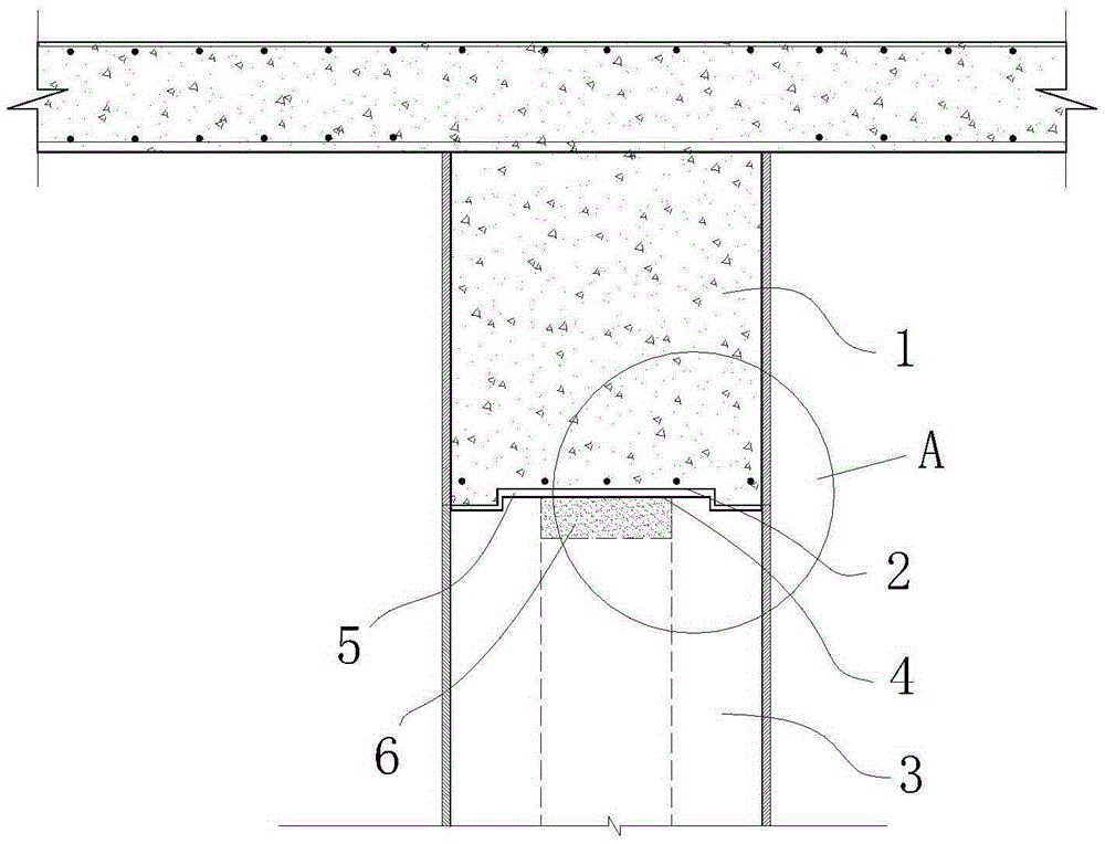
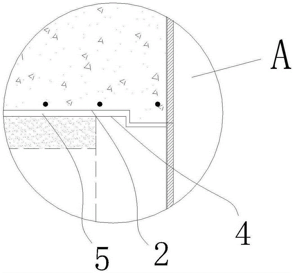
[0021] refer to figure 1 with figure 2 The present invention provides an embodiment of an installation node between a prefabricated hollow wall panel and a cast-in-place concrete wall panel, which is the installation node between a prefabricated hollow wall panel 3 and a cast-in-place concrete beam 1 on an outer wall, and the lower end surface of the cast-in-place concrete beam 1 forms a concave Groove 2, the groove 2 extends along the longitudinal direction of the cast-in-place concrete beam 1, and the groove 2 is recessed 20mm inward from the lower end surface of the cast-in-place concrete beam 1.

[0022] The upper end surface of the prefabricated hollow wall panel 3 of the outer wall forms a raised strip 4 matching the groove 2 on the lower end surface of the cast-in-place concrete beam 1, and the raised strip 4 extends along the longitudinal direction of the prefabricated hollow wall panel 3 of the outer wall. Pressure grouting is performed between the lower end surface...

Embodiment 2

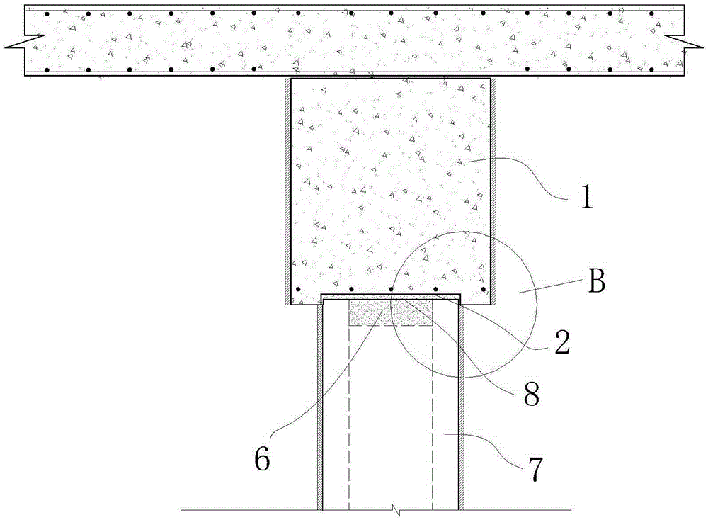
[0025] refer to image 3 with Figure 4 , the present invention provides an embodiment of a prefabricated hollow wall panel and a cast-in-place concrete wall panel installation node, which is an installation node between a prefabricated hollow wall panel 7 and a cast-in-place concrete beam 1 on an interior wall, and the cast-in-place concrete beam 1 in this embodiment Same as Example 1, the upper end surface of the prefabricated hollow wall panel 7 for the inner wall is a plane, and the distance between the two walls of the prefabricated hollow wall panel 7 for the inner wall is slightly smaller than the groove 2 formed by the lower end surface of the cast-in-place concrete beam 1. The distance from the inner side, so that the upper end of the prefabricated hollow wall panel 7 of the inner wall can be embedded in the groove 2, and pressure grouting is performed between the lower end surface of the cast-in-place concrete beam 1 and the upper end surface of the prefabricated hol...


PUM


Abstract

The invention provides a prefabricated hollow wall panel and cast-in-place concrete wall panel mounting node which comprises a cast-in-place concrete beam. A groove is formed in the lower end face of the cast-in-place concrete beam. The groove extends along the longitudinal direction of the cast-in-place concrete beam. According to the prefabricated hollow wall panel and cast-in-place concrete wall panel mounting node provided by the invention, the cast-in-place concrete beam with the groove in the lower end face is used; both sides of the groove are flanged; the balance stability of the cast-in-place concrete beam is greatly improved; and seismic fortification and water resistance are realized.

Description

technical field [0001] The invention relates to the installation node of prefabricated hollow wall panels and cast-in-situ concrete wall panels. Background technique [0002] In the prior art, there is no uniform installation specification for prefabricated concrete prefabricated hollow light wall panels. Now the common practice is to use steel pull-pieces to connect beams and panels with nails or expansion screws. Seismic fortification and external wall waterproofing cannot Effective solution. Contents of the invention [0003] The invention aims to provide a prefabricated hollow wall panel and an installation node of the cast-in-place concrete wall panel, which can effectively solve the problems of anti-seismic fortification and waterproofing of the outer wall. [0004] The invention provides a prefabricated hollow wall panel and a cast-in-place concrete wall panel installation node, including a cast-in-place concrete beam, the lower end surface of the cast-in-place con...

Claims


Application Information

Patent Timeline
Patent Type & Authority Applications(China)
IPC IPC(8): E04B2/64
Inventor 王爱志许雷黄鹏易文翔
Owner GUANGDONG CONSTAR CONSTR GRP CO LTD
Why Eureka
Try Eureka