
Power-driven system and vehicle with same

A technology of power drive and power output shaft, applied in the field of vehicles, can solve the problems of the large mass of the casing and the bevel gear, the excessive axial dimension of the differential structure, etc., and achieve the effect of compact structure

Active Publication Date: 2017-04-05
BYD CO LTD
View PDF7 Cites 2 Cited by
  • Summary
  • Abstract
  • Description
  • Claims
  • Application Information

AI Technical Summary

Problems solved by technology

[0003] However, this differential uses a symmetrical bevel gear structure to realize the inter-wheel differential, which is only a partial innovation for the traditional symmetrical bevel gear differential, and cannot really solve the problem that the axial size of this differential structure is too large , shell and bevel gear mass and the shortcomings of relative deviation of reliability

Method used


Image

  • Power-driven system and vehicle with same
  • Power-driven system and vehicle with same
  • Power-driven system and vehicle with same

Examples


Embodiment Construction

[0055] Embodiments of the present invention are described in detail below, examples of which are shown in the drawings, wherein the same or similar reference numerals designate the same or similar elements or elements having the same or similar functions throughout. The embodiments described below by referring to the figures are exemplary and are intended to explain the present invention and should not be construed as limiting the present invention.

[0056] In describing the present invention, it should be understood that the terms "center", "longitudinal", "transverse", "length", "width", "thickness", "upper", "lower", "front", " Orientation or position indicated by "back", "left", "right", "vertical", "horizontal", "top", "bottom", "inner", "outer", "clockwise", "counterclockwise", etc. The relationship is based on the orientation or positional relationship shown in the drawings, and is only for the convenience of describing the present invention and simplifying the descrip...


PUM


Abstract

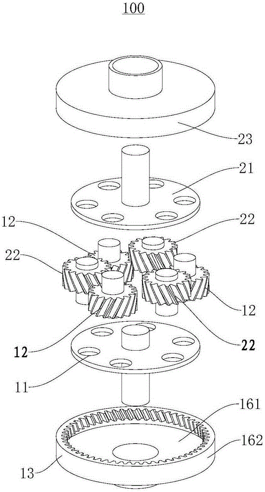
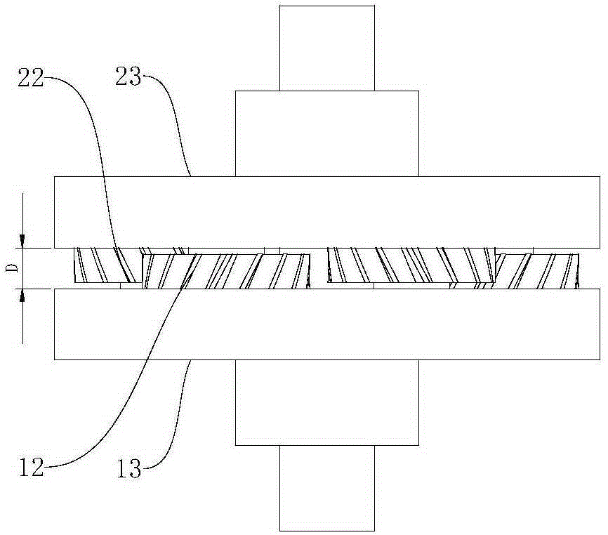
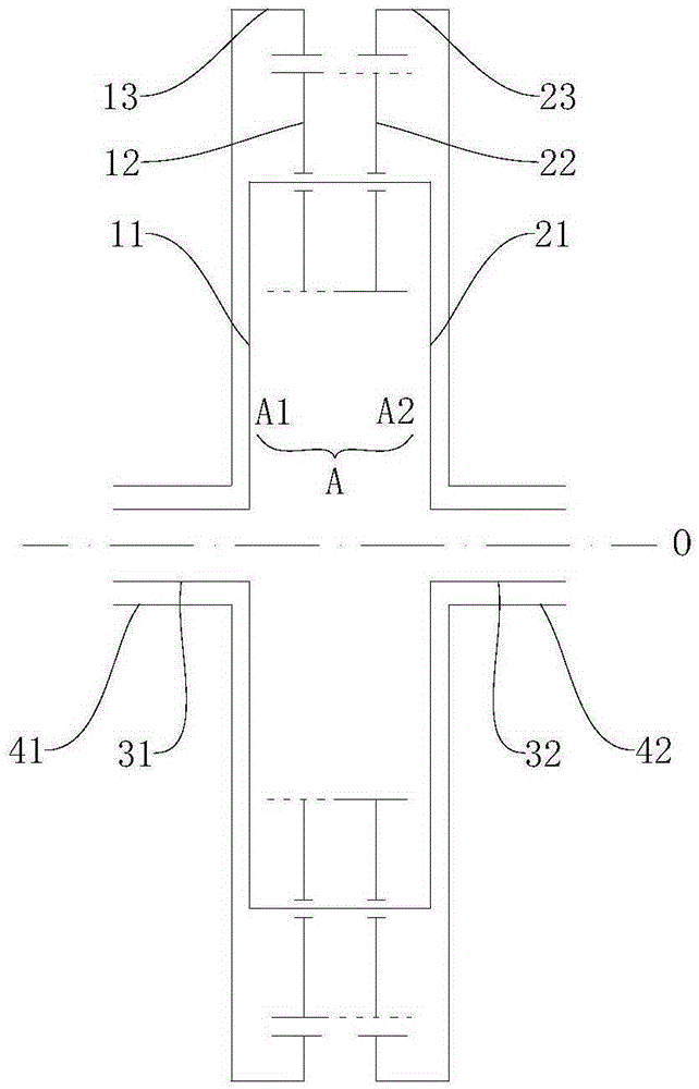
The invention discloses a power-driven system and a vehicle. The power-driven system comprises a differential mechanism, a power output shaft, a plurality of input shafts, a first output part, a second output part, a first motor generator and a second motor generator; the differential mechanism comprises a first planet carrier, a second planet carrier, a first planet wheel, a second planet wheel, a first gear ring and a second gear ring, the first planet wheel and the second planet wheel are arranged on the first planet carrier and the second planet carrier correspondingly and are meshed with the first gear ring and the second gear ring correspondingly, and the second planet wheel is further meshed with the first planet wheel; the power output shaft is arranged to be in linkage with the power input end of the differential mechanism; each input shaft is arranged to be in linkage with the power output shaft; the first output part and the second output part are linked with the first gear ring and the second gear ring correspondingly; and the first motor generator and the second motor generator are linked with the first output part and the second output part correspondingly. The differential mechanism of the power-driven system achieves the differential function on the basis of the planet differential principle, and the structure is compact and simple.

Description

technical field [0001] The invention relates to a power drive system for a vehicle, a vehicle with the power drive system. Background technique [0002] In a kind of differential gear technology that the inventor understands, differential gear comprises the driven gear of final reducer (main reduction and driven gear), planetary gear, sun gear etc., and planetary gear is installed on slave gear by square shaft, bushing. The sub-plate of the movable gear is meshed with the center wheel, and its rotation and movement functions are realized by the rotating pair and the planar moving pair. moment purpose. This kind of differential cancels the original left and right differential housings, planetary gear shafts and other components, and uses square shafts and bushings to directly install the planetary gears on the sub-plate of the driven gear of the main reducer, effectively The number of parts of the differential is reduced, the structure is simplified and the weight is reduce...

Claims


Application Information

Patent Timeline
Patent Type & Authority Applications(China)
IPC IPC(8): F16H48/06B60K17/16
CPCB60K17/16F16H48/06
Inventor 凌和平翟震郑峰徐友彬罗永孟
Owner BYD CO LTD
Learn More