
Pipe-laying installation device for jacking construction of concrete bell and spigot pipes

An installation device and jacking technology, applied in the direction of pipes/pipe joints/fittings, pipe laying and maintenance, mechanical equipment, etc., can solve the problems of pipeline installation quality can not be guaranteed, pipelines are easily deflected, and pipeline sealing is damaged , to achieve the effect of ensuring straightness and standardization, low labor intensity and reducing failure rate

Inactive Publication Date: 2017-04-05
LUOYANG MUNICIPAL CONSTR GRP CORP +1
View PDF8 Cites 1 Cited by
  • Summary
  • Abstract
  • Description
  • Claims
  • Application Information

AI Technical Summary

Problems solved by technology

Among them, the operation is inconvenient, the speed is slow, and the labor intensity is high when the chain hoist is used for installation; due to the large volume of the concrete socket pipe during manual installation, mechanical cooperation or multi-person cooperation is required for installation, and the labor intensity is high. The tube is prone to deflection, thereby destroying the tightness of the entire pipeline
When using these two piping methods for pipeline installation, not only the operation is irregular and the work efficiency is low, but also the installation quality of the pipeline cannot be guaranteed, and the phenomenon of pipeline leakage is often prone to occur.
[0003] In the existing technology of municipal public construction equipment, there is no device that can make the installation of the concrete socket socket pipe in the pipeline pipe arrangement standard and reliable in quality.

Method used


Image

  • Pipe-laying installation device for jacking construction of concrete bell and spigot pipes
  • Pipe-laying installation device for jacking construction of concrete bell and spigot pipes
  • Pipe-laying installation device for jacking construction of concrete bell and spigot pipes

Examples


Embodiment Construction

[0021] Below in conjunction with accompanying drawing, the present invention is described in further detail:

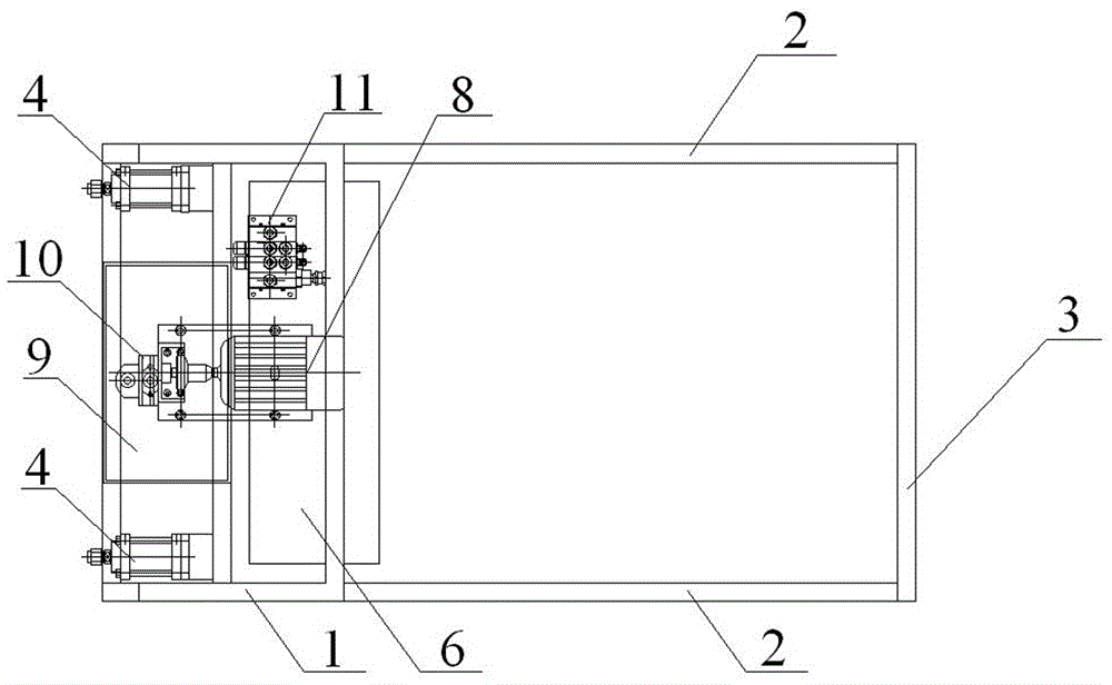
[0022] A pipe installation device for concrete socket pipe jacking construction, comprising a frame 1, a walking wheel set installed at the bottom of the frame 1, a hydraulic propulsion mechanism arranged on the frame 1, and a frame hinged at the rear end of the frame 1 Push rod assembly, travel wheel set comprises travel wheel 6 and auxiliary wheel 7, wherein, travel wheel 6 is arranged on frame 1 near one end of push rod assembly, and auxiliary wheel 7 is arranged on frame 1 end away from push rod assembly, and travel wheel 6 and the number of auxiliary wheels 7 are two, and the diameter of the traveling wheel 6 is greater than the diameter of the auxiliary wheels 7, and the bottom of the frame 1 is also installed to limit the positions of the traveling wheels 6 and the auxiliary wheels 7 the locking device.

[0023] The push rod assembly includes two rear seat pos...


PUM


Abstract

Provided is a pipe-laying installation device for jacking construction of concrete bell and spigot pipes. The pipe-laying installation device comprises a rack, a traveling wheel set installed at the bottom of the rack, a hydraulic propulsion mechanism disposed on the rack, and a push pole assembly hinged to a rear end of the rack. The push pole assembly is composed of two recoil poles and a handle pole. The two recoil poles are symmetrically disposed at two ends of the handle pole, such that the push pole assembly is of a U-shaped frame structure as a whole, and an open end of the push pole assembly of the U-shaped frame structure is hinged to the rack. The hydraulic propulsion mechanism comprises hydraulic cylinders. Piston rods of the hydraulic cylinders extend and retract to achieve fit jacking butting of the spigot of a rear concrete bell and spigot pipe and the bell of a previous concrete bell and spigot pipe. The installation device provided by the present invention has the advantages of simple structure, convenience in construction, reliable pipe laying quality, good pipeline bell-and-spigot joint leakproofness and seldom water leakage with improved working efficiency and reduced labor intensity.

Description

technical field [0001] The invention relates to the technical field of mechanical equipment for urban municipal engineering construction, in particular to a pipe installation device for jacking construction of concrete socket socket pipes of rainwater and sewage pipes. Background technique [0002] At present, in the laying and assembly process of rain and sewage pipelines in urban municipal projects, reinforced concrete socket pipes are commonly used in municipal drainage projects. For the installation of concrete socket pipes, chain hoists or manual handling and lifting are often used to carry out pipeline operations. pipe installation. Among them, the operation is inconvenient, the speed is slow, and the labor intensity is high when the chain hoist is used for installation; due to the large volume of the concrete socket pipe during manual installation, mechanical cooperation or multi-person cooperation is required for installation, and the labor intensity is high. The tu...

Claims


Application Information

Patent Timeline
Patent Type & Authority Applications(China)
IPC IPC(8): F16L1/036
CPCF16L1/036
Inventor 高国强张丽艳李团阳裴建设刘华智刘俊丽张杰
Owner LUOYANG MUNICIPAL CONSTR GRP CORP
Learn More