
Measuring device and measuring method for systematic error detection

A technology for measuring device and system error, applied in the monitoring/testing of direction finder, synchronous device, radio wave directional device, etc. using radio waves, to achieve the effect of simple determination and precise determination

Active Publication Date: 2020-12-04
ROHDE & SCHWARZ GMBH & CO KG
View PDF7 Cites 0 Cited by
  • Summary
  • Abstract
  • Description
  • Claims
  • Application Information

AI Technical Summary

Problems solved by technology

However, the measurement device and method suffer from the problems mentioned above

Method used


Image

  • Measuring device and measuring method for systematic error detection
  • Measuring device and measuring method for systematic error detection
  • Measuring device and measuring method for systematic error detection

Examples


Embodiment Construction

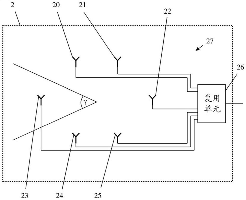
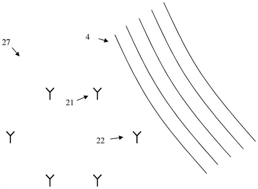
[0082] First, along the Figure 1 to Figure 2 The general structure of an embodiment of the measuring device of the present invention is shown. along Figure 3a , Figure 3b , Figure 3c , Figure 4a , Figure 4b and Figure 4c , the problems of the invention and the functionality of different embodiments of the measuring device and method of the invention are discussed in detail. along Figure 5 and Figure 6 , describes the detailed structure of embodiments of the measuring device of the present invention and their respective functions. along Figure 7 , discusses possible ways of displaying measurements. Finally, about Figure 8 , an embodiment of the measurement method of the present invention is discussed in detail. Similar entities and reference numerals in different drawings have been partially omitted.

[0083] exist figure 1 In , an embodiment of the measuring device 1 of the invention is shown. The measuring device of the invention comprises an antenna...


PUM


Abstract

The invention relates to a measuring device and a measuring method for systematic error detection. The measuring device comprises a processing unit (32), a first antenna adapted to receive a first signal and a second antenna adapted to receive a second signal. The processing unit (32) comprises a baseline unit (321) adapted to determine a baseline variance of the first variable and / or the second variable. Furthermore, the processing unit (32) comprises a variance unit (322) adapted to determine the variance of the first variable and / or the second variable. The first variable and the second variable are at least initially derived from at least the first signal and the second signal, respectively. The processing unit (32) further comprises an error unit (324) adapted to determine whether a systematic error exists based on the baseline variance and the variance of the first variable and / or the second variable.

Description

technical field [0001] The invention relates to determining systematic errors in measurement signals of at least two antennas, especially in direction finding applications. Background technique [0002] When determining the direction of the source of a signal, ideally the signal travels directly from the signal source to the measurement device that determines the direction of the source. However, this ideal situation cannot always be met in practice. In practice, multipath propagation and other effects that lead to systematic errors can occur. This negatively affects the direction of determining the source. Significant errors in the direction of the determined source can be caused by the effects described above. [0003] International patent application WO 2014 / 135196 A1 has shown an efficient measuring device and an efficient method for direction finding. However, this measuring device and method suffers from the problems mentioned above. Contents of the invention ...

Claims


Application Information

Patent Timeline
Patent Type & Authority Patents(China)
IPC IPC(8): G01R29/08H04W72/54
CPCG01R29/08G01S3/023H04W56/0035H04W72/541H04L5/005H04W24/10H04W72/04
Inventor 昂德里克·巴尔特科
Owner ROHDE & SCHWARZ GMBH & CO KG
Learn More