
Time sequence decoder

A decoder and timing technology, applied in the field of timing decoders, can solve the problems of speeding up data transmission, waste of resources, etc., and achieve the effects of multi-chip selection output, strong versatility, and strong decoding ability

Active Publication Date: 2017-04-05
DONGHUA UNIV
View PDF3 Cites 2 Cited by
  • Summary
  • Abstract
  • Description
  • Claims
  • Application Information

AI Technical Summary

Benefits of technology

This patented technology allows for faster processing times by analyzing signals with specific patterns that occur during certain stages or cycles within them. It also improves upon existing designs' capabilities due to its ability to process multiple types of input simultaneously without sacrificing accuracy. Overall, this design makes it possible to perform complex computations at very fast speeds while maintaining accurate results over longer periods of time compared to older methods like analog techniques.

Problems solved by technology

The technical problem discussed in this patented text relates to improving the efficiency of decoded circuits (DC) due to their limitations such as lack of space availability or excessive power consumption. These issues lead to wasted resource usage when trying to achieve higher levels of functionality within smaller chambers. To overcome these challenges, researchers explored new methods like dynamic programming techniques and programmable logic controller technologies.

Method used


Image

  • Time sequence decoder
  • Time sequence decoder
  • Time sequence decoder

Examples


Embodiment Construction

[0059] The present invention will be further described below in combination with specific embodiments. It should be understood that these examples are only used to illustrate the present invention and are not intended to limit the scope of the present invention. In addition, it should be understood that after reading the teachings of the present invention, those skilled in the art can make various changes or modifications to the present invention, and these equivalent forms also fall within the scope defined by the appended claims of the present application.

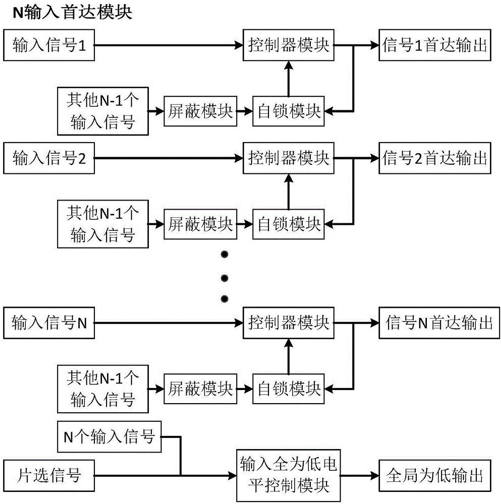
[0060] An n-input Shouda module, the Shouda module is a coupling control circuit composed of logic gate circuits, including one chip selection signal input and at least two timing signal inputs; the chip selection signal is a continuously input high-level signal; the timing The signal is a high-level signal or a low-level signal input at intervals;

[0061] For each timing signal input:

[0062] This signal is used as ...


PUM


Abstract

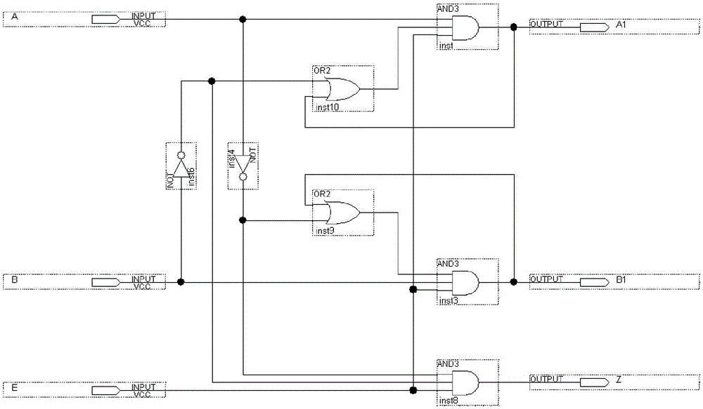
The invention relates to a time sequence decoder. The time sequence decoder is composed of an input time sequence decoder and first arrival modules in serial connection and in parallel connection. The first arrival module is a coupling control circuit, and comprises a path of chip select signal input and at least two paths of time sequence signal input; each path of time sequence signal input is mainly composed of a NOT gate, three input AND gates and two input Or gates; the output of each path of signals is influenced by all input ends; the single path of input also influences output of each path of signals; the serial connection is that first arrival modules with different input signal paths are sequentially connected according to the number of input signal paths; and the parallel connection is that the first arrival modules with the same input signal paths are parallelly connected in different serial connection circuits, and the first arrival modules at two ends of the first arrival modules with the same input signal paths have the same input signal paths respectively. According to the time sequence decoder, in a condition with the same input signal paths, the decoding ability can be significantly improved, more output signal lines can be obtained, and the data transmission speed can be quickened.

Description


Claims


Application Information

Patent Timeline
Owner DONGHUA UNIV
Learn More