Nailing machine

A nailing machine and stapling technology, applied in the field of nailing machines, can solve the problems of cumbersome and complicated binding process, unfavorable automatic mechanical production, etc., and achieve the effect of improving work efficiency and ensuring work efficiency

Pending Publication Date: 2017-04-19
漳州市伯廉机械设备有限公司
View PDF0 Cites 3 Cited by
  • Summary
  • Abstract
  • Description
  • Claims
  • Application Information

AI Technical Summary

Problems solved by technology

[0003] The traditional nailing machine requires manual loading of staples before it can be bound. The binding p

Method used


Image

  • Nailing machine
  • Nailing machine
  • Nailing machine

Examples


Embodiment Construction

[0025] The present invention will be further described below in conjunction with the accompanying drawings and specific embodiments.

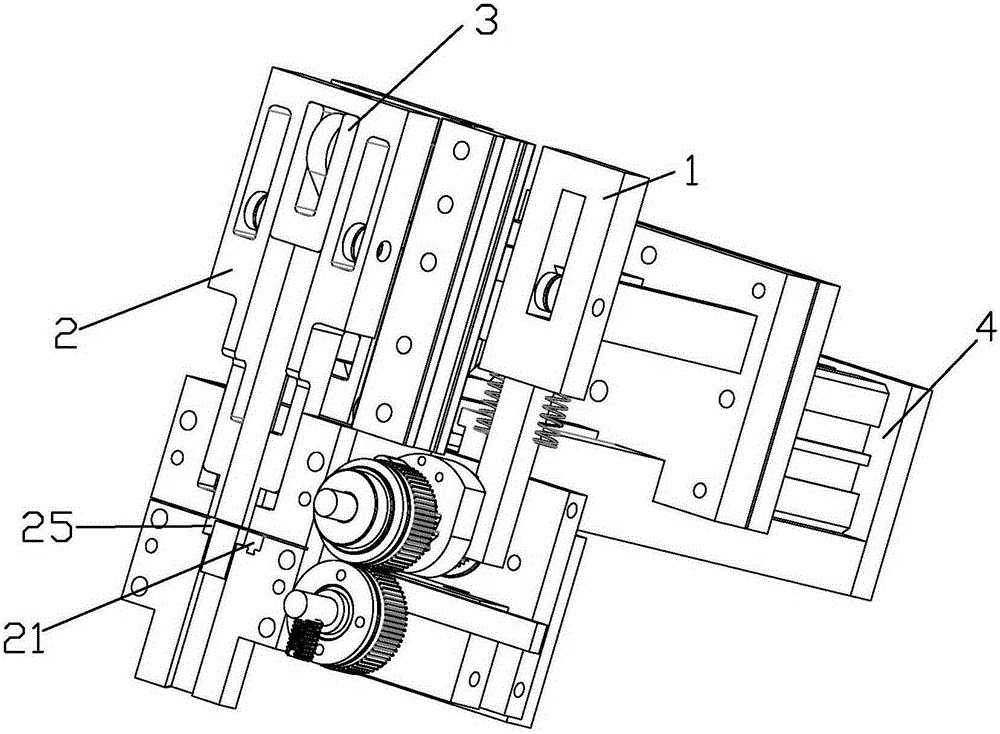
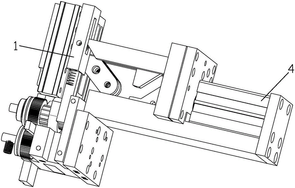
[0026] refer to Figure 1-2 , a nailing machine, comprising: a wire feeding mechanism 1, a shear forming mechanism 2, a nailing mechanism 3, and a driving mechanism 4 for driving the above mechanisms; in this embodiment, the driving mechanism 4 is an air cylinder.

[0027] The wire feeding mechanism 1 sends the metal wire into the shearing and forming mechanism 2 with a fixed length, and the shearing and forming mechanism 2 cuts the metal wire and presses down to form a door-shaped staple; the nailing mechanism 3. Push out the staples to complete the nailing. Therefore, the above-mentioned nailing machine can automatically complete the making and nailing of the staples without manual loading of the staples, which greatly improves the work efficiency.

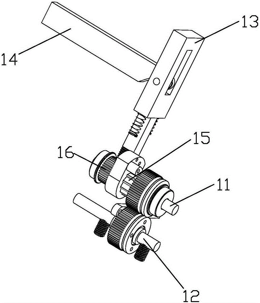
[0028] further reference Figure 3-4 , the wire feeder, 1 includes an upper wire feed whee...


PUM


Abstract

The present invention provides a nailing machine, which comprises a wire feeding mechanism, a shearing molding mechanism, a nailing mechanism and a driving mechanism for driving the mechanisms to work, wherein the wire feeding mechanism feeds a metal wire into the shearing molding mechanism at a fixed length, the shearing molding mechanism cuts the metal wire and performs pressing molding to obtain a door-shaped nail, and the nailing mechanism ejects the nail so as to complete the nailing. The invention provides the nailing machine, which can automatically complete the nail production and the nailing without filling of the nail so as to improve the working efficiency.

Description

technical field [0001] The invention relates to a binding device, in particular to a nailing machine. Background technique [0002] In woodworking, decoration, leather and other operations, it is often necessary to use nails to combine objects. In order to improve the working efficiency and nailing effect, the industry has developed a nailing machine that can continuously nail. It is mainly formed on the bottom of the casing. The nail groove group is used for accommodating nail needles and is automatically fed. In addition, there is a nail driving piece on the front edge of the casing that can be strongly fired downward by the action of the elastic member. When the nail driving piece is selectively lifted up by the pressure handle, the bottom The nails in the nail groove group will enter the firing position of the nailing piece one by one, so when the nailing piece is released by the pressure handle and fired downward, the nails located below can be driven out forcefully, so...

Claims


Application Information

Patent Timeline
IPC IPC(8): B25C1/04
Inventor 许伯廉
Owner 漳州市伯廉机械设备有限公司
Why Eureka
Try Eureka