
Dual-layer piling device

A double-layer, pile-body technology, which is applied to sheet pile walls, buildings, and foundation structure engineering, can solve problems such as waste of resources, potential safety hazards of superstructures, and inconvenient construction, and achieve convenient operation, firm pile operation, The effect of simple structure

Inactive Publication Date: 2017-04-19
尹瑜
View PDF2 Cites 0 Cited by
  • Summary
  • Abstract
  • Description
  • Claims
  • Application Information

AI Technical Summary

Problems solved by technology

This piling method needs to waste more resources and equipment
During the piling operation, due to the limitation of the diameter of the pile body, after the pile operation is completed, the pile body remains in the ground, the diameter of the pile body remains unchanged, and the force points are all made of the pile body, and the pile body is unevenly received from top to bottom, affecting construction of superstructure
The piles are left in the ground as necessary reserved parts, which cannot be reused repeatedly, wasting resources
In addition, the traditional pile driver is prone to defective piles during use. The traditional treatment methods include expanding the cap, re-pile in situ, connecting piles, sinking the pile core, filling piles, drilling reinforcement, changing the construction method or modifying the design plan.
Some major pile foundation accidents are difficult to deal with and cost a lot of money
Once defective piles appear, adopting one of the above audit methods will result in increased cost and expenditure, and may cause defects after the overall design is changed.
Therefore, it is easy to cause inconvenient construction by using traditional pile drivers to reserve piles underground. Once defective piles appear, it will cause lags in production and construction period, and bring huge economic losses to the construction party. bring security risks

Method used


Image

  • Dual-layer piling device
  • Dual-layer piling device
  • Dual-layer piling device

Examples


Embodiment Construction

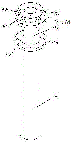
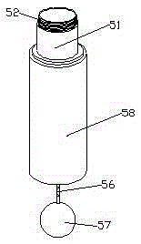
[0014] Such as figure 1 , 2 , shown in 3, a kind of double-deck piling device, comprises pile outer tube 42, the inside of described pile outer tube 42 is set with pile inner tube 43, is connected with pile head 58 below the pile outer tube 42, pile head The top of 58 is provided with the inner pipe connection head 51 that is connected with pile body pipe 43, and described pile head 58 is hollow structure, and inner pipe connection head 51 is connected with pile head 58, passes iron chain below pile head 58 56 active connections have plug 57.

[0015] The pile outer tube 42 is set on the outside of the pile inner tube 43, the top of the pile outer tube 42 is provided with a first connection plate 46, the first connection plate 46 is provided with a first connection hole 49, the top of the pile inner tube 43 A second connection plate 47 is provided, and a second connection hole 61 matching with the first connection hole 49 is opened on the second connection plate 47, and a su...


PUM


Abstract

The invention relates to a dual-layer piling device. A pile inner tube is arranged in a pile outer tube; the bottom of the pile outer tube is connected to a pile head; an inner tube connection joint connected to the pile inner tube is arranged on the top of the pile head; the pile head is of a hollow structure; the inner connection joint communicates with the pile head; the bottom of the pile head is connected to a plug through an iron chain; and the pile outer tube and the pile inner tube are mutually connected through bolts. The pile outer tube and the pile inner tube move downward at the same time, a piling work is completed, and then an external pouring device is used to put a cement pouring material to the inner tube to fill a hole formed by the pile outer tube while the pile inner tube move upward, the pouring work of cement piles can be achieved, piles will not be reserved underground, and piling and pouring can be completed at the same time; and natural piles can be formed after solidification, secondary pouring can be avoided, and firm piling of piles formed by a cement filling material can be achieved.

Description

technical field [0001] The invention relates to the field of machinery, in particular to a piling device, in particular to a double-layer piling device. Background technique [0002] The pile driver is composed of pile hammer, pile frame and auxiliary equipment. The pile hammer is attached to two parallel vertical guide rods at the front of the pile frame, commonly known as the gantry, and is hoisted with a lifting hook. The pile frame is a steel structure tower frame, and a hoist is provided at the rear of it for lifting piles and pile hammers. There is a guide frame composed of two guide rods in front of the pile frame, which is used to control the direction of pile driving, so that the pile can accurately penetrate into the ground according to the designed orientation. Pile hammers can be divided into drop hammers, steam hammers, diesel hammers, hydraulic hammers, etc. according to the power source of the movement. A pile driver is a pile machine that uses impact force...

Claims


Application Information

Patent Timeline
Patent Type & Authority Applications(China)
IPC IPC(8): E02D15/04E02D5/66
Inventor 尹瑜尹宛玫梁铎高峰杨艳薛红勋杨清波杨红岩
Owner 尹瑜
Learn More