Three-phase switch

A three-phase switching and switching technology, which is applied in the direction of electronic switches, electrical components, pulse technology, etc., can solve problems such as production and life impact, impact on residents' use, branch circuit power outages, etc.

Inactive Publication Date: 2017-04-19
STATE GRID CORP OF CHINA +3
View PDF9 Cites 1 Cited by
  • Summary
  • Abstract
  • Description
  • Claims
  • Application Information

AI Technical Summary

Problems solved by technology

However, the working principle of the traditional switch is relatively mechanical, and the circuit can only be disconnected by manual control. When the circuit is disconnected, the branch circuit will be powered off, affecting the use of residents, affecting production and life, and manual operation is not safe.

Method used


Image

  • Three-phase switch
  • Three-phase switch
  • Three-phase switch

Examples


Embodiment Construction

[0012] Below in conjunction with accompanying drawing, the present invention will be further described:

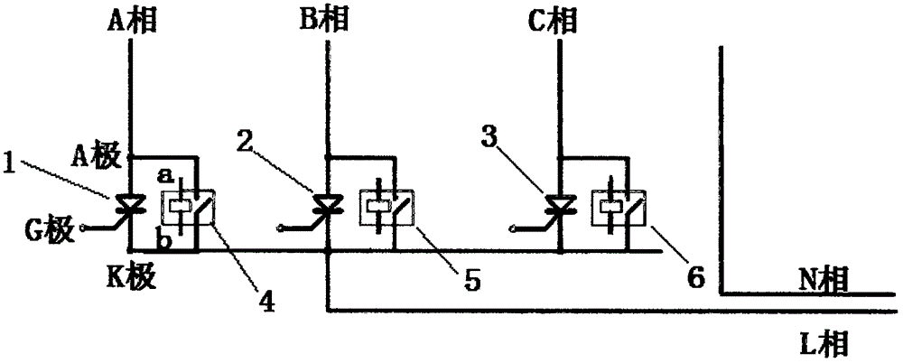
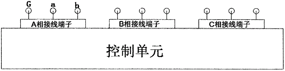
[0013] Such as figure 1 and figure 2 As shown, the three-phase changeover switch has A, B, and C three-phase incoming terminals, on which thyristor 1, thyristor 2, and thyristor 3 are respectively connected in series, and each thyristor has A pole, K pole, and G pole, and the AC contact The device 4 is connected in parallel to the A pole and the K pole of the thyristor 1. Similarly, the AC contactor 5 is connected in parallel with the thyristor 2, and the AC contactor 6 is connected in parallel with the thyristor 3. A, B, and C three-phase incoming line terminals converge into one point to form L phase and enter the household, and form a loop with N phase. The control unit has connecting terminals connected with ABC three-phase respectively, and the connecting terminals of phase A are connected with the G pole of the thyristor 1 and the a and b poles of the AC contactor...


PUM


Abstract

The invention discloses a three-phase switch which comprises three inlet ends. Three inlet ends are converged to form an outlet end. Each inlet end is connected in series with a thyristor. Three alternating current contactors are connected in parallel with the respective thyristor. Each thyristor and alternating current contactor are connected with a control unit. The switch can automatically switch among three phases without power off, which is safe and convenient.

Description

technical field [0001] The invention relates to a device, in particular to an itemized operation switch for single-phase users. Background technique [0002] In power supply, adjusting the three-phase load balance of A, B, and C is of great significance to ensure the healthy operation of the power supply system. Phase overall balance. However, the working principle of the traditional switch is relatively mechanical, and the circuit can only be disconnected by manual control. When the circuit is disconnected, the branch circuit will be powered off, affecting the use of residents, affecting production and life, and manual operation is not safe. Contents of the invention [0003] The purpose of the present invention is to provide a three-phase switching switch, which can automatically switch between three phases without power interruption, which is safe and convenient. [0004] To achieve the above object, the present invention takes the following technical solutions: [0...

Claims


Application Information

Patent Timeline
Patent Type & Authority Applications(China)
IPC IPC(8): H03K17/72
CPCH03K17/72
Inventor 平凡潘龙屹石小梦赵志成陈红松徐凯薛占钰毕根平
Owner STATE GRID CORP OF CHINA
Why Eureka
Try Eureka