A low temperature drift delay circuit

A delay circuit, low-temperature drift technology, applied in electrical components, electronic switches, pulse technology, etc., can solve the problems of integrated oscillator single-stage delay effects, etc., achieve simple structure, fast conduction speed, and reduce device area Effect

Active Publication Date: 2022-03-18
HUAZHONG UNIV OF SCI & TECH
View PDF11 Cites 0 Cited by
  • Summary
  • Abstract
  • Description
  • Claims
  • Application Information

AI Technical Summary

Problems solved by technology

[0004] Aiming at the defects and improvement needs of the prior art, the present invention provides a low-temperature drift delay circuit, the purpose of which is to solve the problem that the single-stage delay of the on-chip integrated oscillator is affected when the temperature and power supply voltage change

Method used


Image

  • A low temperature drift delay circuit
  • A low temperature drift delay circuit
  • A low temperature drift delay circuit

Examples


Embodiment Construction

[0031] In order to make the object, technical solution and advantages of the present invention clearer, the present invention will be further described in detail below in conjunction with the accompanying drawings and embodiments. It should be understood that the specific embodiments described here are only used to explain the present invention, not to limit the present invention. In addition, the technical features involved in the various embodiments of the present invention described below may be combined with each other as long as they do not constitute a conflict with each other.

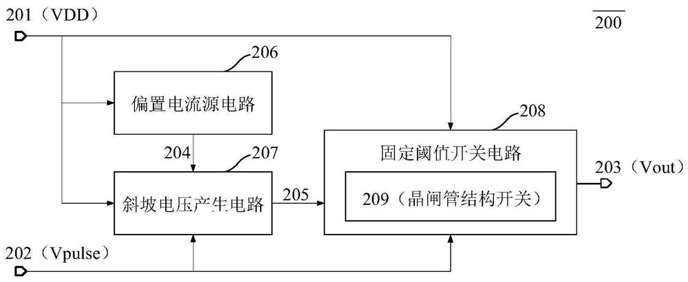
[0032] figure 2 A schematic structural diagram of the oscillator circuit 200 proposed by the present invention includes a bias current source circuit 206 , a ramp voltage generation circuit 207 and a fixed threshold switch circuit 208 .

[0033] Specifically, the negative temperature coefficient current bias 204 generated by the bias current source circuit 206 is mirrored to the slope voltage ...


PUM


Abstract

The invention discloses a low-temperature drift delay circuit. The circuit includes: a bias current source circuit, a slope voltage generating circuit and a fixed threshold switch circuit; the bias current source circuit is used to generate a negative temperature coefficient current bias, Its input terminal is connected to the power supply voltage, and its output terminal is connected to the slope voltage generating circuit; the bias input terminal of the slope voltage generating circuit is connected to the output terminal of the bias current source circuit, and its digital signal input terminal is connected to the digital signal input , the output terminal of which is connected to the fixed threshold switch circuit; the input terminal of the pull-down switch of the fixed threshold switch circuit is connected to the output terminal of the slope voltage generating circuit, the input terminal of the pull-up switch is connected to the digital signal input, and the output terminal of the fixed threshold switch circuit is delayed subsequent digital signals. The invention can perform time-delay processing on digital signals without being affected by temperature and power supply voltage; the fixed threshold switch circuit adopts a thyristor structure as a pull-down switch, and has the advantages of stable threshold value, high speed, simple structure and the like.

Description

technical field [0001] The invention belongs to the technical field of analog integrated circuits, and in particular relates to a low-temperature drift delay circuit. Background technique [0002] As all kinds of electrical appliances have higher and higher requirements for switching power supply chips, the design of switching power supply chip has higher and higher requirements for the oscillator inside the chip. The impact of the operating frequency of a switching power supply chip on chip performance involves parameters such as ripple, loop stability, and maximum load, and even indirectly affects the chip's input voltage range and small signal response speed. Due to the different thermal power generated by the chip under different loads and the temperature change of the environment, the chip works at different temperatures, and the different temperature characteristics of the devices under different processes make the output frequency of the oscillator also affected by te...

Claims


Application Information

Patent Timeline
Patent Type & Authority Patents(China)
IPC IPC(8): H03K17/284
CPCH03K17/284
Inventor 邹雪城尚泽元邹志革童乔凌皮庆广
Owner HUAZHONG UNIV OF SCI & TECH
Why Eureka
Try Eureka