
Bogie for railway vehicle and railway vehicle with same

A railway vehicle and bogie technology, which is applied to the operating mechanism of railway vehicle brakes, bogies, railway car body components, etc., can solve the problem of inability to reduce the lateral pressure of curved roads, and achieve the effect of suppressing the fluctuation of wheel weight.

Active Publication Date: 2018-07-24
NIPPON STEEL CORP
View PDF10 Cites 0 Cited by
  • Summary
  • Abstract
  • Description
  • Claims
  • Application Information

AI Technical Summary

Problems solved by technology

Therefore, the bogies disclosed in Patent Document 3 and Patent Document 4 cannot reduce the lateral pressure on curved roads.

Method used


Image

  • Bogie for railway vehicle and railway vehicle with same
  • Bogie for railway vehicle and railway vehicle with same
  • Bogie for railway vehicle and railway vehicle with same

Examples


no. 1 Embodiment approach

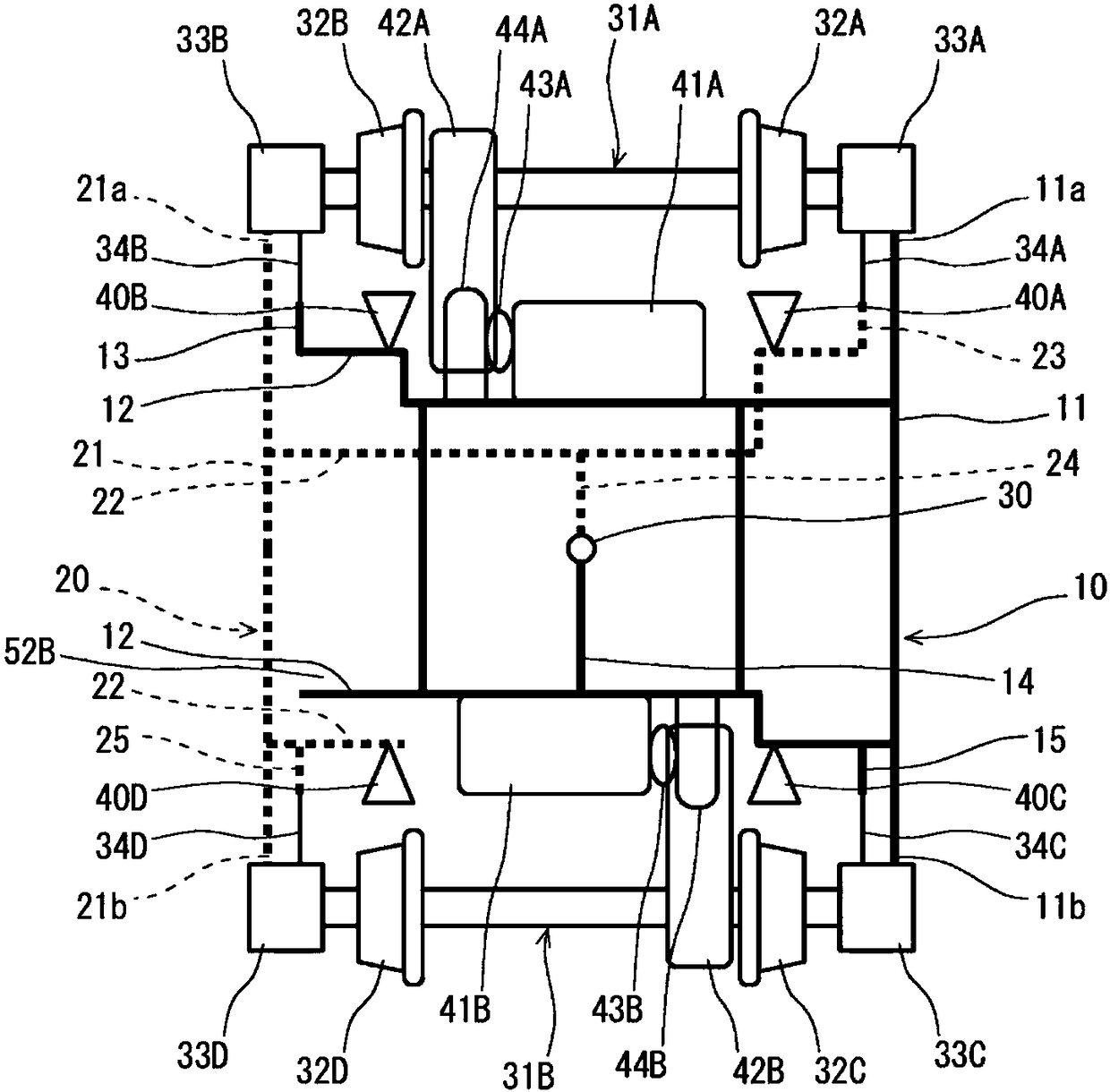
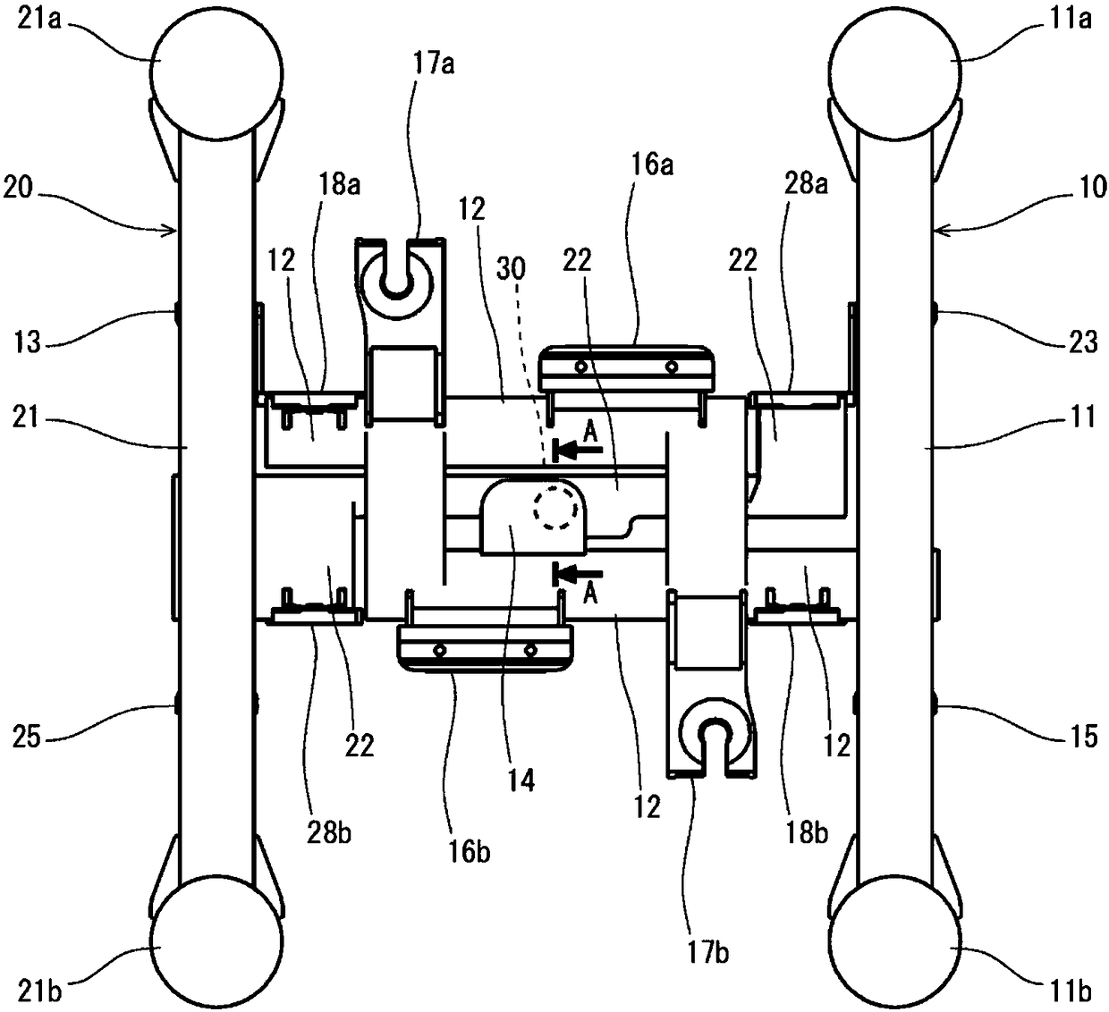
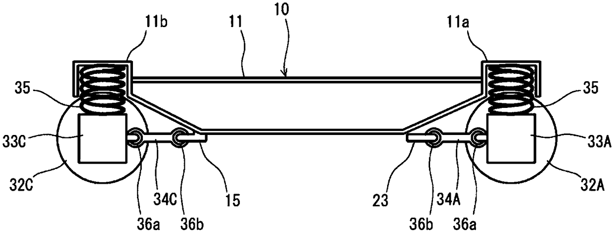
[0082] figure 1 It is a plan view schematically showing an example of the railway vehicle bogie according to the first embodiment of the present invention. figure 2 yes means figure 1 It is a plan view of a specific example of a bogie frame used in the shown railway car bogie. Figure 3A yes figure 1 The right side view of the bogie for the railway vehicle shown, Figure 3B is the left side view of the bogie. Figure 4 yes figure 2 A-A sectional view of the bogie for the railway vehicle shown.

[0083] Such as figure 1 and figure 2 As shown, the bogie of the first embodiment includes a first frame body 10 and a second frame body 20 that are independent from each other as a bogie frame. The bogie frame is formed by combining the first frame body 10 and the second frame body 20 . exist figure 1 In the figure, in order to easily understand the structure of the first frame body 10 and the second frame body 20, the constituent elements of the first frame body 10 a...

no. 2 Embodiment approach

[0121] Figure 8 It is a plan view schematically showing an example of the railway vehicle bogie according to the second embodiment of the present invention. Figure 9 yes means Figure 8 It is a plan view of a specific example of a bogie frame used in the shown railway car bogie. Figure 10A yes Figure 8 The right side view of the bogie for the railway vehicle shown, Figure 10B is the left side view of the bogie. The second embodiment is based on the configuration of the above-mentioned first embodiment, and descriptions that overlap with the first embodiment are appropriately omitted. The same applies to the third to seventh embodiments described later. exist Figure 8 in, with the figure 1 Similarly, the constituent elements of the first housing 10 are indicated by thick solid lines, and the constituent elements of the second housing 20 are indicated by thick dotted lines.

[0122] In the second embodiment, if Figure 8 , Figure 9 as well as Figure 10B As sh...

no. 3 Embodiment approach

[0128] Figure 11 It is a plan view schematically showing an example of a railway vehicle bogie according to a third embodiment of the present invention. Figure 12 yes means Figure 11 It is a plan view of a specific example of a bogie frame used in the shown railway car bogie. The third embodiment is a modification of the structure of the second embodiment described above. exist Figure 11 in, with the figure 1 Similarly, the constituent elements of the first housing 10 are indicated by thick solid lines, and the constituent elements of the second housing 20 are indicated by thick dotted lines.

[0129] In the third embodiment, the formation position of the first protruding piece 14 in the front-rear direction and the formation position of the second protruding piece 24 in the front-rear direction are aligned on the left and right. There is no particular limitation as long as the formation position of the first protruding piece 14 in the front-rear direction and the fo...


PUM


Abstract

The present invention provides a railway vehicle bogie and a railway vehicle having the same. A bogie for a railway vehicle includes: a first frame body (10) having a right side beam (11); a second frame body (20) having a left side beam (21); and an axle box support device , which has a connecting rod (34A-34D) extending from each axle box (33A-33D). The two frame bodies (10, 20) are combined by means of an elastic element (30). The front right axle box (33A) is supported by the front end (11a) of the first frame (10), and the link (34A) is coupled to the extension (23) extending from the second frame (20). The front left axle box (33B) is supported by the front end (21a) of the second frame (20), and the link (34B) is coupled to the extension (13) extending from the first frame (10). The right rear axle box (33C) is supported by the rear end (11b) of the first frame (10), and the link (34C) is coupled to the side beam (11) of the first frame (10). The left rear axle box (33D) is supported by the rear end (21b) of the second frame (20), and the link (34D) is coupled to the side beam (21) of the second frame (20).

Description

technical field [0001] The present invention relates to a bogie for a railway vehicle, in particular to a bogie capable of realizing self-guiding of front and rear axles and a railway vehicle including the bogie and a vehicle body. Background technique [0002] A rail vehicle consists of a car body and a bogie, which travels on rails. When a railway vehicle passes through a curved road, the force that the wheels press against the track in the left and right directions is generated, which is the so-called lateral pressure. As the lateral pressure increases, the risk of derailment increases, so it is desirable to keep the lateral pressure low. In addition, for the force that the wheels press the track in the vertical direction, that is, the so-called wheel weight, the wheel weight of the wheels on the outer rail side becomes smaller in the section where the track twists, especially in the section where the exit of the curved road eases the curve. When the wheel weight become...

Claims


Application Information

Patent Timeline
Patent Type & Authority Patents(China)
IPC IPC(8): B61F5/40B61F5/52B61H1/00
CPCB61H13/00F16D49/16B61H1/00B61F5/44B61F3/04B61F5/301
Inventor 龟甲智下川嘉之中居拓自水野将明
Owner NIPPON STEEL CORP
Features
  • Generate Ideas
  • Intellectual Property
  • Life Sciences
  • Materials
  • Tech Scout
  • Unparalleled Data Quality
  • Higher Quality Content
  • 60% Fewer Hallucinations
Learn More