
A vibrating liquid crystal screen dismantling tool structure

A liquid crystal screen and vibrating technology, which is applied in the field of liquid crystal screen dismantling tool structure, can solve the problems of glass plate damage due to force, high scrap rate, high price, etc., achieve the goals of reducing lateral pressure, preventing damage, and improving dismantling efficiency Effect

Active Publication Date: 2018-04-03
ZHONGSHAN TUODIAN ELECTRONICS TECH
View PDF10 Cites 0 Cited by
  • Summary
  • Abstract
  • Description
  • Claims
  • Application Information

AI Technical Summary

Problems solved by technology

[0002] In the production and assembly of LCD screens, a glass plate needs to be aligned and bonded to the front surface of the LCD module. During this process, the glass plate and the LCD module will inevitably be misaligned and produce defective products. Defective glass plates and liquid crystal components are detached and rebonded. At present, the dismantling of liquid crystal screens is usually carried out manually. Since the glass plates of existing liquid crystal screens are very thin, the glass plates are easily broken during manual dismantling. Scrap, and the glass plate of the LCD screen, especially the large-size LCD screen or touch LCD screen, is expensive. If the scrap rate is too high, the production cost of the LCD screen will be greatly increased.
In addition, there are also a small number of manufacturers that use dismantling machines to disassemble the LCD screen. These dismantling machines usually use a blade to insert into the gap between the LCD module and the glass plate to cut the adhesive glue to separate the glass plate. The connection between the colloid and the liquid crystal module and the glass plate is relatively firm. The blade of the existing dismantling machine only moves and cuts along the working direction, which will generate a large lateral pressure on the colloid and the glass plate, which will easily cause the glass plate to be stressed. oversized and damaged

Method used


Image

  • A vibrating liquid crystal screen dismantling tool structure
  • A vibrating liquid crystal screen dismantling tool structure
  • A vibrating liquid crystal screen dismantling tool structure

Examples


Embodiment Construction

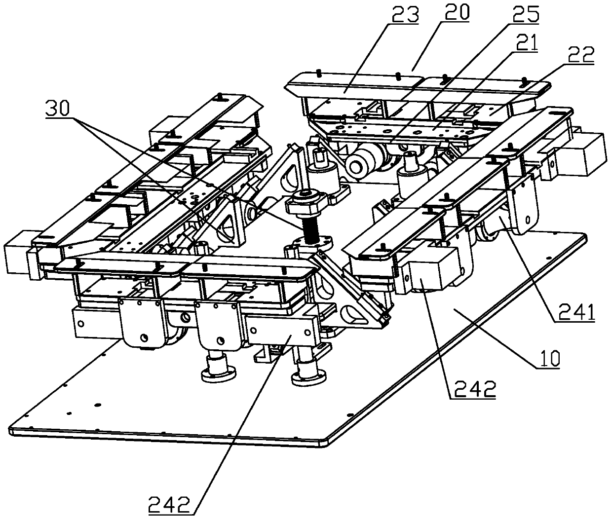
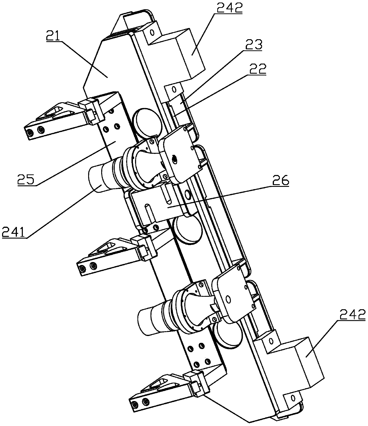
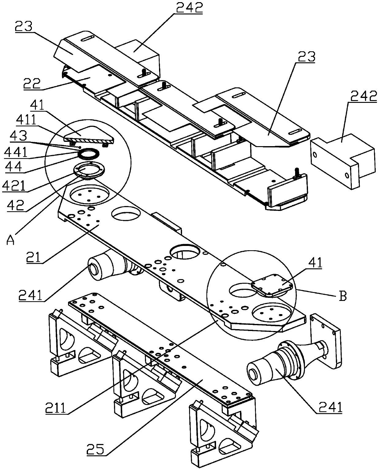
[0022] refer to Figure 1 to Figure 7 , a vibrating liquid crystal screen dismantling cutter structure, comprising a frame 10, at least one blade assembly 20 slidably arranged on the frame 10 and a driving device 30 for driving the blade assembly 20 to work forward, the blade assembly 20 includes A base 21, a blade holder 22 slidably arranged on the base 21 and at least one dismantling blade 23 arranged on the blade holder 22, the blade assembly 20 is provided with at least one vibrating device, which is used to drive the blade The seat 22 makes it vibrate back and forth relative to the base 21, so that the dismantling blade 23 on the blade seat 22 can vibrate to grind and cut the colloid, so that the dismantling blade 23 is easier to cut the colloid, improves the dismantling efficiency, and can effectively Reduce the lateral pressure on the glass plate and prevent the glass plate from being damaged due to excessive force. The dismantling blade 23 in this embodiment is in the...


PUM


Abstract

The invention discloses a vibration type liquid crystal screen detaching tool structure which comprises a stander, at least one blade assembly arranged on the stander in a sliding manner, and a driving device for driving the blade assembly to realize working feed, wherein each blade assembly comprises a base, a blade seat arranged on the base in a sliding manner and at least one detaching blade arranged on the blade seat; at least one vibration device is arranged on each blade assembly and is used for driving each blade seat to do reciprocating vibration relative to the base. According to the vibration type liquid crystal screen detaching tool structure, the vibration devices are arranged on the blade assemblies, so that the detaching blades on the blade seats can generate vibration to grind colloid; therefore, the detaching blades can cut the colloid open more easily, the detaching efficiency is improved, the transverse pressure on a glass plate can be effectively reduced, and damage caused by overhigh stress on the glass plate is prevented.

Description

technical field [0001] The invention relates to a liquid crystal screen dismantling machine, in particular to a liquid crystal screen dismantling tool structure. Background technique [0002] In the production and assembly of LCD screens, a glass plate needs to be aligned and bonded to the front surface of the LCD module. During this process, the glass plate and the LCD module will inevitably be misaligned and produce defective products. Defective glass plates and liquid crystal components are detached and rebonded. At present, the dismantling of liquid crystal screens is usually carried out manually. Since the glass plates of existing liquid crystal screens are very thin, the glass plates are easily broken during manual dismantling. Scrap, and LCD screens, especially large-size LCD screens or touch LCD screens, have a relatively high glass plate price. If the scrap rate is too high, the production cost of LCD screens will be greatly increased. In addition, there are also a...

Claims


Application Information

Patent Timeline
Patent Type & Authority Patents(China)
IPC IPC(8): G02F1/13
CPCG02F1/1303
Inventor 刘洪云赵七星林志成
Owner ZHONGSHAN TUODIAN ELECTRONICS TECH
Features
  • Generate Ideas
  • Intellectual Property
  • Life Sciences
  • Materials
  • Tech Scout
  • Unparalleled Data Quality
  • Higher Quality Content
  • 60% Fewer Hallucinations
Learn More