
Railway vehicle bogie and railway vehicle provided with the same

A railway vehicle and bogie technology, which is applied in the field of railway vehicle bogies, can solve the problem of difficult recovery of the wheel and axle, and achieve the effects of reducing lateral pressure and suppressing the change of wheel load.

Active Publication Date: 2022-03-15
NIPPON STEEL CORP
View PDF5 Cites 0 Cited by
  • Summary
  • Abstract
  • Description
  • Claims
  • Application Information

AI Technical Summary

Problems solved by technology

Therefore, especially in the process of the railway vehicle from the exit transitional curve section to the straight line section, it is difficult for the wheel axle to return to the standard posture

Method used


Image

  • Railway vehicle bogie and railway vehicle provided with the same
  • Railway vehicle bogie and railway vehicle provided with the same
  • Railway vehicle bogie and railway vehicle provided with the same

Examples


Embodiment

[0087] In order to confirm the effects of the present invention, numerical simulation analysis was carried out. Specifically, various models of vehicles including one vehicle body and two steerable bogies were produced, and the conditions of traveling on a curved path were simulated by numerical analysis using the models. As the curved path, a curved path including five sections (A: entrance straight line section, B: entrance transitional curve section, C: stable curve section, D: exit transitional curve section, and E: exit straight line section) was employed. The radius of curvature of the stable curve section C is set to 200 m (curvature: 0.005). The main conditions of the model are shown in Table 1 below.

[0088] [Table 1]

[0089] distinguish Bolster support Connection of bolster to bogie frame Example Center bearing part (1 place) Shaft and hole (including rubber bushing) Past example side bearing (two places) heart plate Comparati...


PUM


Abstract

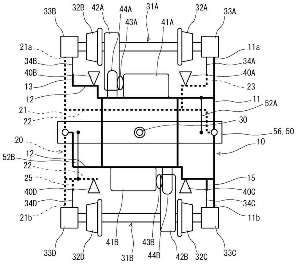
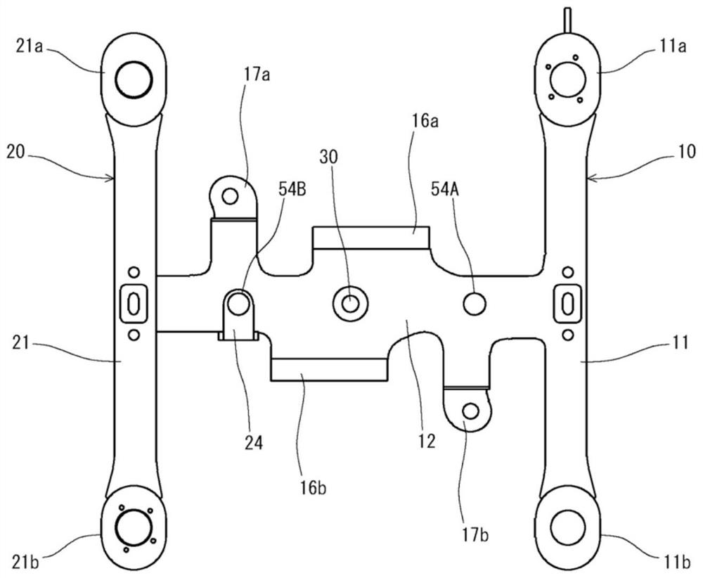
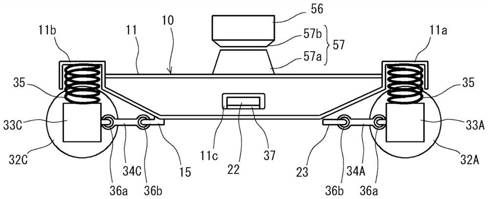
The bogie includes: a first frame (10) including a right side beam (11) and a first beam (12); a second frame (20) including a left side beam (21) and a 2 beams (22); and bolsters (56). The first frame body (10) and the second frame body (20) support each other so as to be slidable in the front-rear direction. The central portion of the bolster (56) is supported by the central bearing portion (30). The bolster (56) and the first crossbeam (12) are flexibly supported by the first connection part (52A) arranged on the right side of the center bearing part (30), and the bolster (56) and the second crossbeam (22) are arranged It is flexibly supported by the second connection part (52B) on the left side of the center bearing part (30). Accordingly, it is possible to suppress fluctuations in lateral pressure and wheel load on the curved path.

Description

technical field [0001] The present invention relates to a bogie for a railway vehicle (hereinafter also simply referred to as a "bogie"), and more particularly to a bogie capable of self-steering front and rear axles, and a railway vehicle including the bogie and a vehicle body. Background technique [0002] A railway vehicle consists of a body and a bogie, and travels on tracks. When a railway vehicle passes a curved path, a force that the wheels press against the rail in the left-right direction, so-called lateral pressure, is generated. In particular, in a section where the track is twisted, such as a gentle curve section at the entrance and exit of a curved path, it is difficult for the wheel shaft to follow the track, so the lateral pressure becomes large. If the lateral pressure is high, the risk of derailment increases. Therefore, it is desirable to keep the lateral pressure low. In addition, regarding the force of the wheels pressing the rail in the vertical direc...

Claims


Application Information

Patent Timeline
Patent Type & Authority Patents(China)
IPC IPC(8): B64F5/40B61C9/38B61F5/10B61F5/14B61F5/30B61F5/40B61F5/52B61H7/00
CPCB61F5/40B61F5/16B61F5/44B61H1/00B61F3/04B61F5/14
Inventor 山崎阳介下川嘉之水野将明
Owner NIPPON STEEL CORP
Features
  • Generate Ideas
  • Intellectual Property
  • Life Sciences
  • Materials
  • Tech Scout
  • Unparalleled Data Quality
  • Higher Quality Content
  • 60% Fewer Hallucinations
Learn More