
Ballast circuit

A ballast and current regulator technology, applied in the field of ballasts and drivers for supplying loads)

Inactive Publication Date: 2017-04-19
AKRUK LTD
View PDF3 Cites 10 Cited by
  • Summary
  • Abstract
  • Description
  • Claims
  • Application Information

AI Technical Summary

Problems solved by technology

Additionally, the current ripple is ideally kept below 2% peak-to-peak over the entire dimming range

Method used


Image

  • Ballast circuit
  • Ballast circuit
  • Ballast circuit

Examples


Embodiment Construction

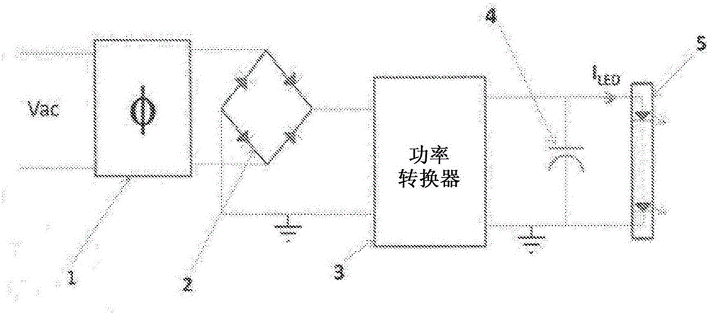
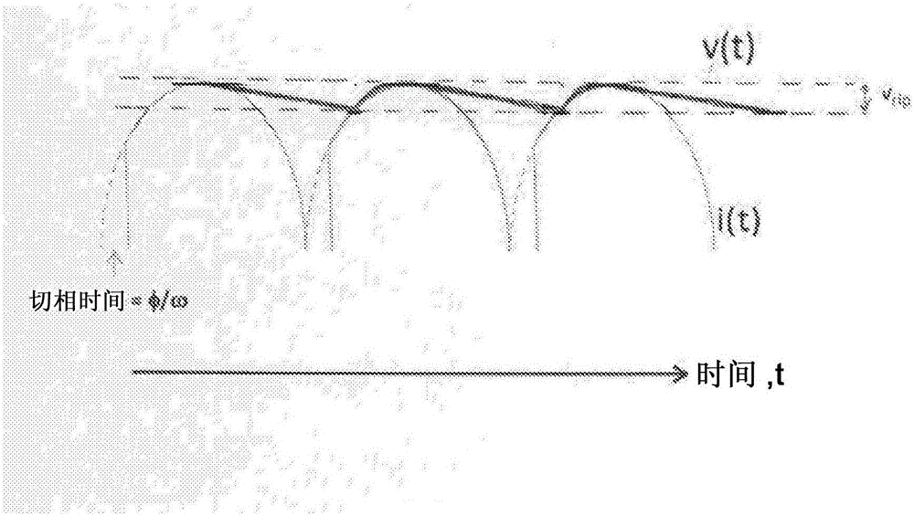
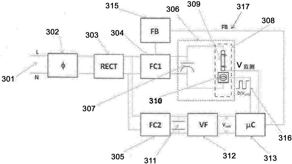
[0074] Figure 3a A functional block diagram is shown of a dimmable LED lighting ballast operating from AC power with some form of modulation, such as phase cutting, in accordance with an embodiment of the present invention, wherein the phase cutting This can be achieved by using either a leading edge phase cutter or a trailing edge phase cutter. exist figure 2The effect of a leading edge phase cutter is illustrated in the input voltage waveform of , where each half cycle of the AC input voltage is blanked or phase cut from the low phase angle end. In the case of a trailing edge phase cutter, each half cycle of the AC voltage waveform is phase cut from the high phase angle end. Throughout the following overview, the role of the ballast based on the functional block diagram in Figure 3 will be explained with reference to the use of a leading edge phase cutter. However, it should be clear to those of ordinary skill in the art that there is an equivalent set of operating cond...


PUM


Abstract

A ballast circuit suitable for driving an LED or similar load, comprises a primary switch mode converter, means for measuring a modulation, such as a phase cut, as used for dimming light levels, on an input AC supply, a current regulator positioned in series with the load, and a feedback controller for controlling operation of the switch mode controller based upon measured modulation levels. The feedback controller is adapted to interrupt normal switching of the switch mode converter if modulation levels detected lead to the ballast working at a lower than desired efficiency (deep dimming), or if voltage levels across the current regulator are higher than desired. The feedback controller may have a further feedback means for controlling switch mode parameters during lower levels of modulation (shallow dimming). The circuit allows large dimming levels to be achieved without generating appreciable light flicker in the load.

Description

technical field [0001] The present invention relates to ballasts and power circuits of the type commonly used to drive variable loads, such as dimmable light emitting diode (LED) lighting arrangements. More particularly, the present invention relates to ballasts and drivers particularly suitable for supplying loads such as LEDs, including organic LEDs (OLEDs), having means for reducing optical flicker that may occur during dimming processes. Background technique [0002] LED lighting is beginning to become the mainstream choice for low-energy lighting. In order for LED technology to fully establish its credentials in the field and meet the current expectations of users, it is for LED-based lighting systems to provide control over the intensity of emitted light in response to "commands" or signals provided by dimming devices. A dimming device is very advantageous. Depending on the age, purpose and architecture of the lighting system, this device can take one of several form...

Claims


Application Information

Patent Timeline
Patent Type & Authority Applications(China)
IPC IPC(8): H05B33/08H05B44/00H05B45/59
CPCH05B45/395H05B45/10H05B45/375H05B45/38H05B45/385H05B45/59Y02B20/30
Inventor 大卫·查尔斯·班尼斯特
Owner AKRUK LTD
Learn More