
Independent braking and controllability control method and system for a vehicle with regenerative braking

a control method and braking technology, applied in the direction of braking systems, braking components, electric propulsion mounting, etc., can solve the problems of degrading controllability, unbalanced braking, degrading vehicle controllability, etc., to reduce understeer and oversteer, improve controllability of a vehicle, and not significantly reduce energy recovery

Inactive Publication Date: 2006-09-12
FORD MOTOR CO
View PDF16 Cites 50 Cited by
  • Summary
  • Abstract
  • Description
  • Claims
  • Application Information

AI Technical Summary

Benefits of technology

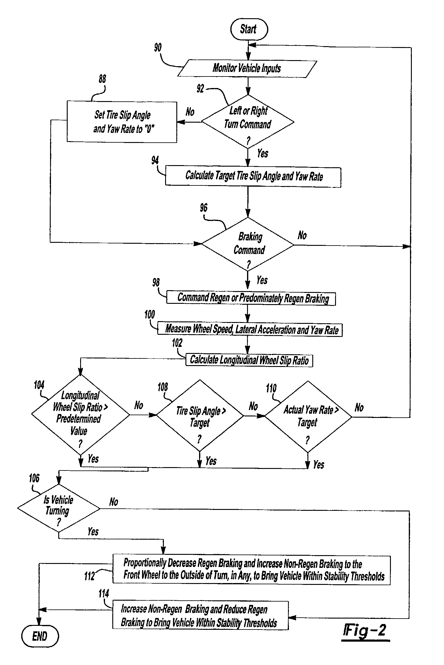
[0013]Accordingly, the present invention provides a method and system to control braking and improve controllability of a vehicle equipped with regenerative braking. The invention can provide regenerative braking while reducing understeer and oversteer while not significantly reducing energy recovery, even on low friction surfaces. The invention detects vehicle oversteer and understeer and correspondingly balances regenerative braking torque with conventional non-regenerative braking torque if controllability decreases.
[0015]In accordance with a related aspect of the invention, the controller can be a simple proportional-integral-derivative feedback type controller.
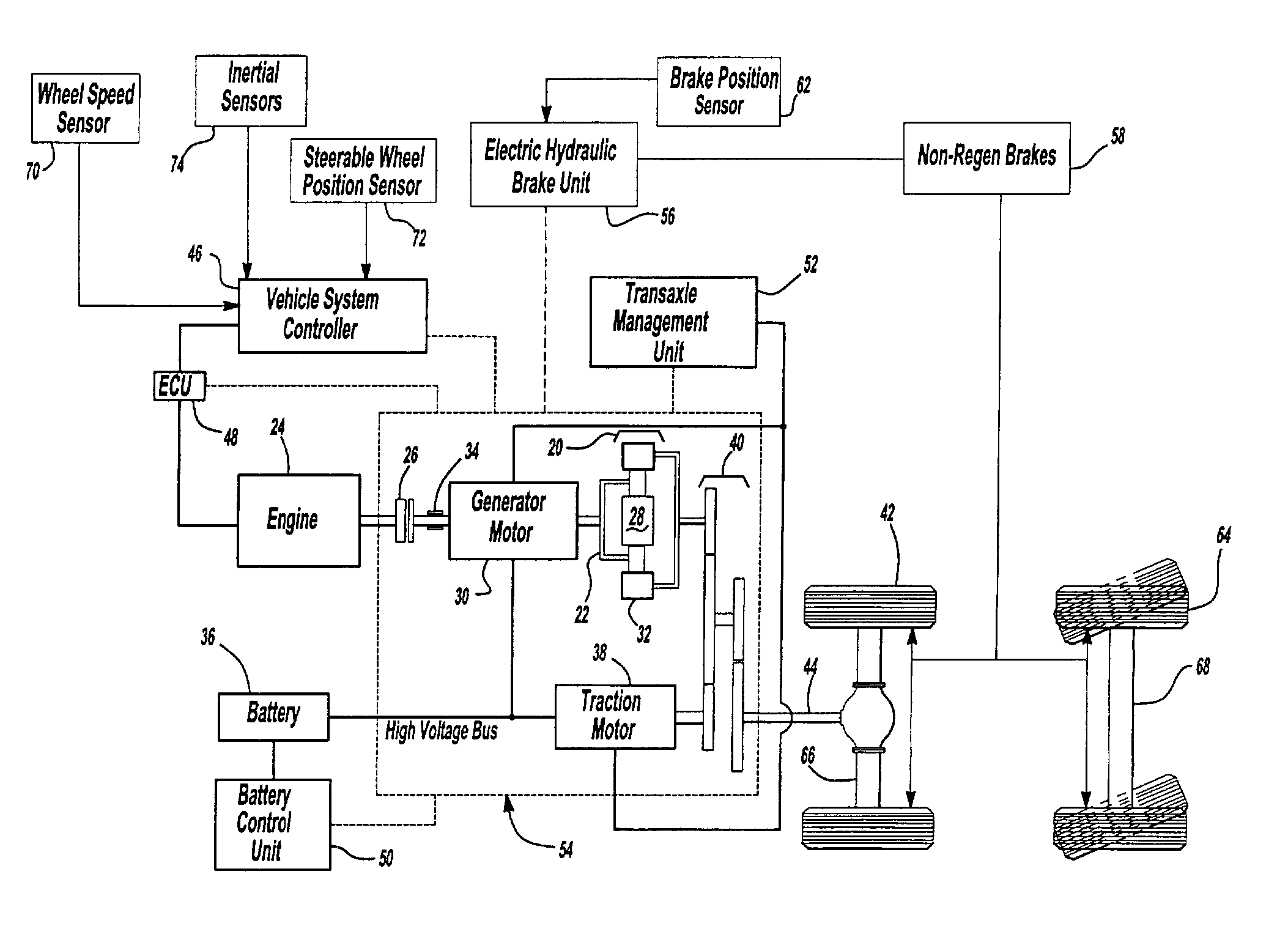
[0016]The invention can reduce oversteer in vehicle configurations where the front axle wheels are steerable. In a preferred configuration the generator motor provides regenerative braking to the wheels on the rear axle, while the non-regenerative brakes are connected to the wheels on the front axle. The sensor input also includes data showing the steering angle in degrees left or right of dead center. Sensors also provide data related to lateral acceleration and yaw rate.
[0018]For a rear wheel drive vehicle, where non-regenerative braking is provided on the front wheels, as regenerative braking in the rear is reduced and the vehicle is in a turn commanded by the operator, the non-regenerative braking for the outside wheel of the turn is increased to reduce oversteer. Since non-regenerative braking is only increased on one wheel, a smaller reduction in the amount of regenerative braking is required. A similar strategy can be used for a front wheel drive vehicle. Here, as regenerative braking is reduced on the front wheels to reduce understeer, the strategy proportionally increases the non-regenerative braking on the rear wheel that is on the inside of the turn. These strategies maximize energy recovery.

Problems solved by technology

The difference between the braking torques can cause unbalanced braking that may degrade vehicle controllability.
Degraded controllability can be in the form of either reduced stability or reduced steerability.
Both of these effects, understeer due to excessive levels of regenerative braking at the front axle and oversteer due to excessive levels of regenerative braking at the rear axle, can become greater on low friction surfaces such as ice and snow.
The requirement for controllability on low friction surfaces typically forces regenerative braking levels to be reduced, resulting in a corresponding loss of energy recovery.
Unfortunately, while these inventions do reduce excessive slip, they do not provide an adequate level of stability because they focus mainly on the maximization of straight line stopping.
Unfortunately, this invention is susceptible to false activation of the mode switchover.
Thus, the ability to distribute brake torque between regenerative and non-regenerative braking while optimizing energy recovery and vehicle controllability constitutes an unmet need in the art.

Method used


Image

  • Independent braking and controllability control method and system for a vehicle with regenerative braking
  • Independent braking and controllability control method and system for a vehicle with regenerative braking
  • Independent braking and controllability control method and system for a vehicle with regenerative braking

Examples


Embodiment Construction

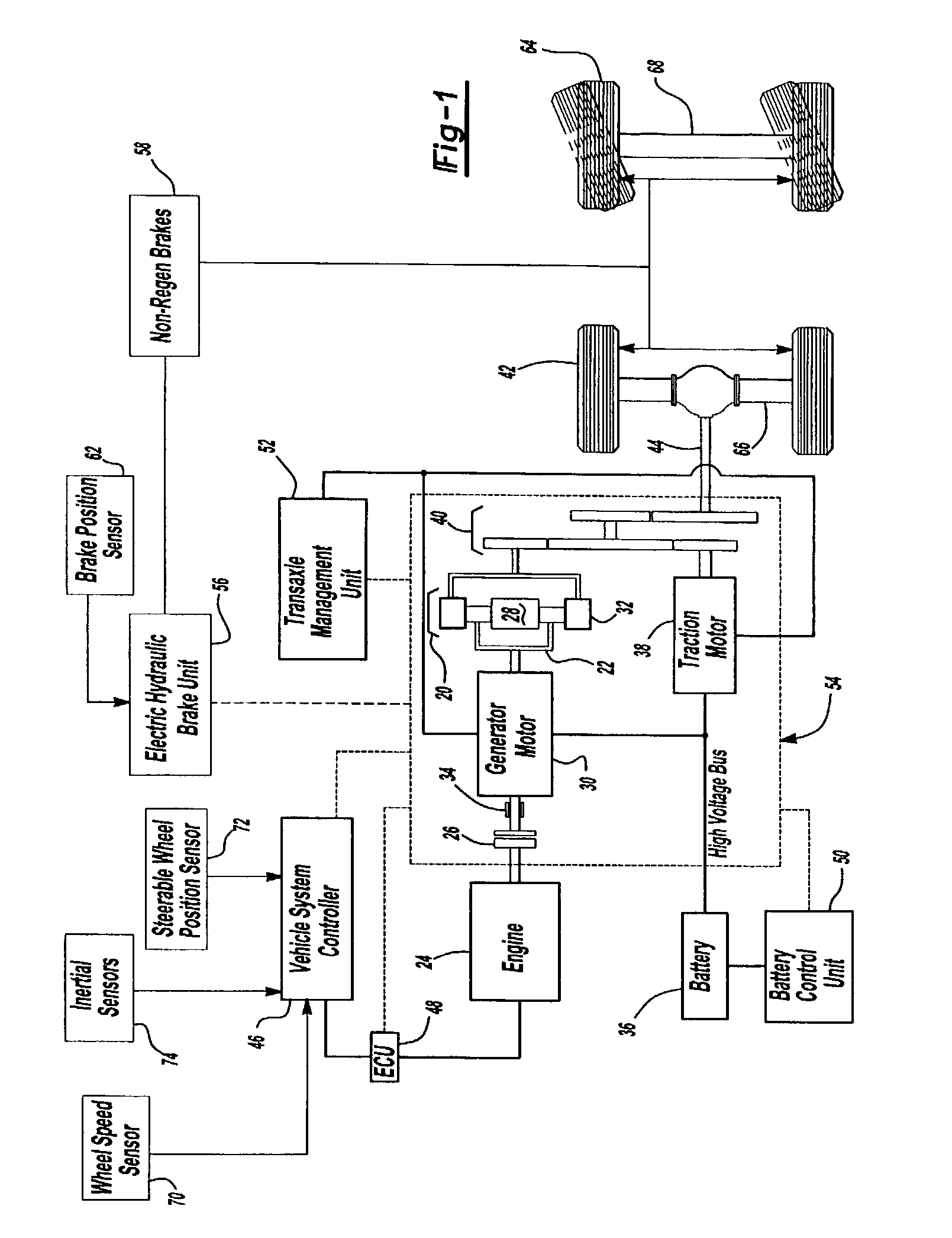
[0023]The present invention relates to electrically propelled vehicles such as electric vehicles (EVs), hybrid electric vehicles (HEVs), and fuel cell electric vehicles (FCEVs) that have a regenerative braking system. The present invention is a system to continuously control braking and controllability for a vehicle with regenerative braking. FIG. 1 demonstrates just one possible configuration, specifically a parallel / series hybrid electric vehicle (split) configuration with rear wheel drive. The present invention can easily be modified to adapt to a front wheel drive vehicle.

[0024]In a basic HEV, a planetary gear set 20 mechanically couples a carrier gear 22 to an engine 24 via a one-way clutch 26. The planetary gear set 20 also mechanically couples a sun gear 28 to a generator motor 30 and a ring (output) gear 32. The generator motor 30 also mechanically links to a generator brake 34 and is electrically linked to a battery 36. A traction motor 38 is mechanically coupled to the rin...


PUM


Abstract

A strategy is provided using feedback control algorithms to monitor and dynamically modify front and rear braking torque to maintain controllability in a vehicle that initially favors regenerative braking. Simple proportional-integral-derivative feedback controllers can be used. The controller can monitor wheel speed, lateral acceleration, yaw rate, and brake position to selectively activate non-regenerative braking independently for each individual wheel and regenerative braking in varying proportion based on at least one actual vehicle controllability value and at least one predetermined target value for controllability and optimization of energy recovery. Controllability factors can include predetermined longitudinal slip ratio, comparison of tire slip angle or yaw rate. For rear wheel drive configurations, the non-regenerative brakes can be applied to just one front axle wheel on the outside of a turn. For front wheel drive configurations, the non-regenerative brakes can be applied to just one rear axle wheel on the inside of a turn.

Description

FIELD OF INVENTION[0001]The present invention relates generally to vehicle braking and controllability control systems, commonly referred to as stability control systems, and specifically to a braking and controllability control method and system for a vehicle with regenerative braking that optimizes energy recovery while reducing vehicle oversteer and understeer by providing braking control for individual non-regenerative braking wheels.BACKGROUND OF INVENTION[0002]The need to reduce fossil fuel consumption and emissions in automobiles and other vehicles predominately powered by internal combustion engines (ICEs) is well known. Vehicles powered by electric motors attempt to address these needs. Another alternative solution is to combine a smaller ICE with electric motors into one vehicle. Such vehicles combine the advantages of an ICE vehicle and an electric vehicle and are typically called hybrid electric vehicles (HEVs). See generally, U.S. Pat. No. 5,343,970 to Severinsky.[0003]...

Claims


Application Information

Patent Timeline
Patent Type & Authority Patents(United States)
IPC IPC(8): B60T13/74B60T8/17B60K1/02B60K6/365B60K6/44B60L7/18B60L7/24B60L50/16B60R16/02B60T8/172B60T8/1755B60T8/24B60T8/26B60T13/58
CPCB60K6/44B60L7/24B60T8/1755B60T8/24B60T8/246B60T8/267B60T13/586B60W30/02B60K6/365B60K1/02Y02T10/92B60L2240/24B60L2240/461B60L2240/465B60T2230/02B60T2270/613B60W2520/14B60W2520/26B60W2520/28B60W2540/12B60W2900/00Y02T10/623B60W2050/0011B60W2540/18Y02T10/62
Inventor BROWN, TODD ALLEN
Owner FORD MOTOR CO
Learn More