LED array driving apparatus and backlight driving apparatus using the same

a technology of led arrays and driving apparatuses, applied in valve housings, process and machine control, instruments, etc., can solve the problems of prior art driving circuits not meeting, luminous flux deviation for each led array, and luminous flux varies for each, etc., to achieve uniform luminance and color.

Inactive Publication Date: 2007-10-02
SAMSUNG ELECTRONICS CO LTD
View PDF7 Cites 59 Cited by
  • Summary
  • Abstract
  • Description
  • Claims
  • Application Information

AI Technical Summary

Benefits of technology

[0012]The present invention has been made to solve the foregoing problems of the prior art and it is therefore an object of the present invention to provide an LED array driving apparatus and a backlight driving apparatus using the same which allows regulation of analogue and PWM dimming for each channel and LED of an LED backlight, thereby achieving uniformity in luminance and color in all regions of a backlight.

Problems solved by technology

However, a Light Emitting Diode (LED) has gained popularity recently as a light source since the CCFL was found to have several problems including environmental pollution due to use of mercury, slow response time of about 15 ms, low color reproductibility of 75% compared with National Television System Committee (NTSC), and generation of pre-set white light.
However, when the above prior art driving circuit is used to drive the LED array with a plurality of LEDs connected in series, luminous flux varies for each LED due to deviation in forward voltage of each LED.
If the backlight with the above described driving circuit is a vertical-descent type with an LED located in the lower part of the display panel, since a plurality of LED arrays are disposed in a predetermined interval to one another, and each LED array has a driving circuit of FIG. 1, independent driving may cause deviation in luminous flux for each LED array.
In other words, a prior art driving circuit cannot satisfy the above described needs and particularly, it has not succeeded in taking advantage of the merit of LED which is being able to change luminance and color temperature.

Method used


Image

  • LED array driving apparatus and backlight driving apparatus using the same
  • LED array driving apparatus and backlight driving apparatus using the same
  • LED array driving apparatus and backlight driving apparatus using the same

Examples


Embodiment Construction

[0027]The following description will present an LED array driving apparatus and a backlight driving apparatus using the same of the invention with reference to the accompanying drawings.

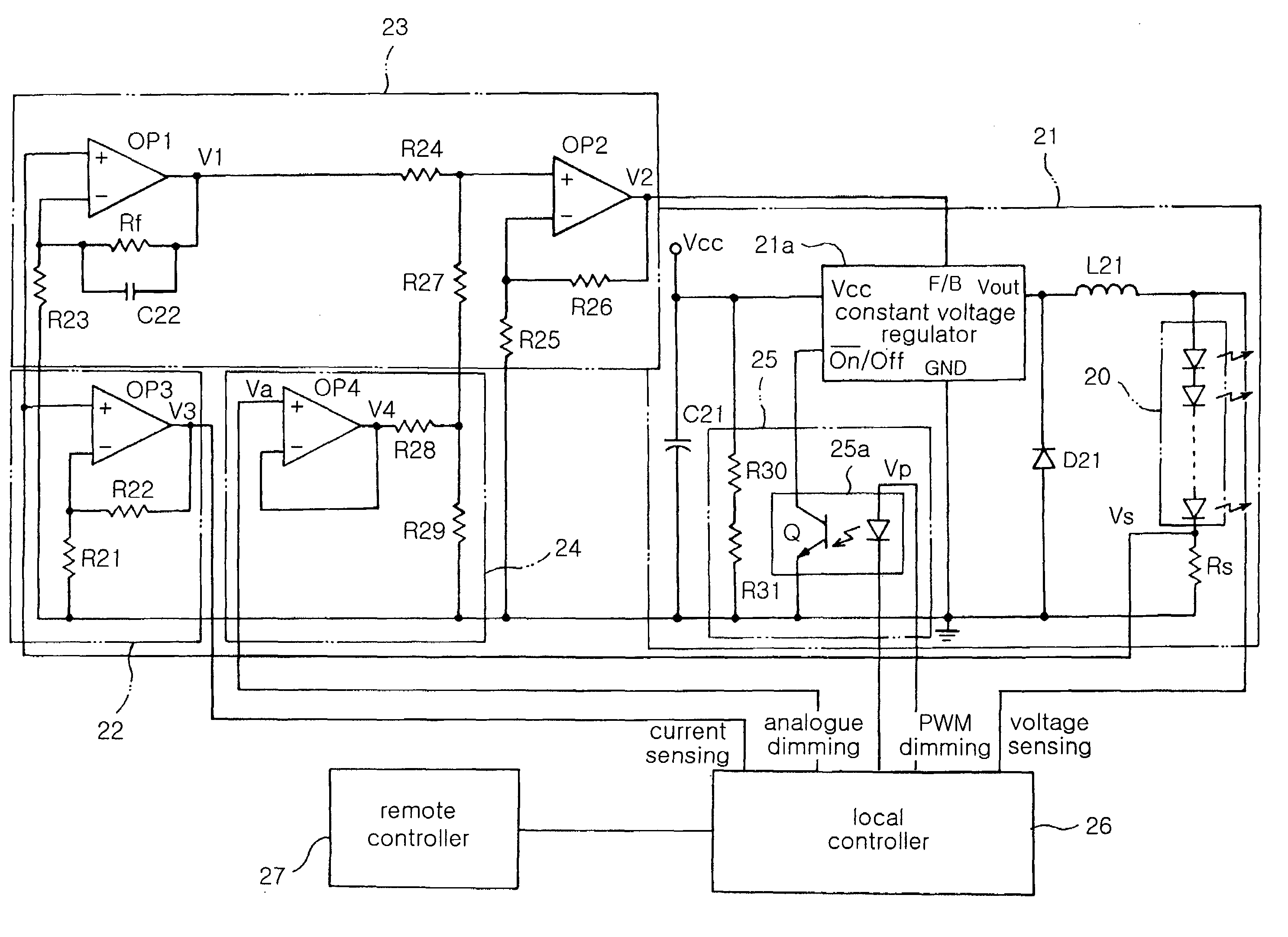
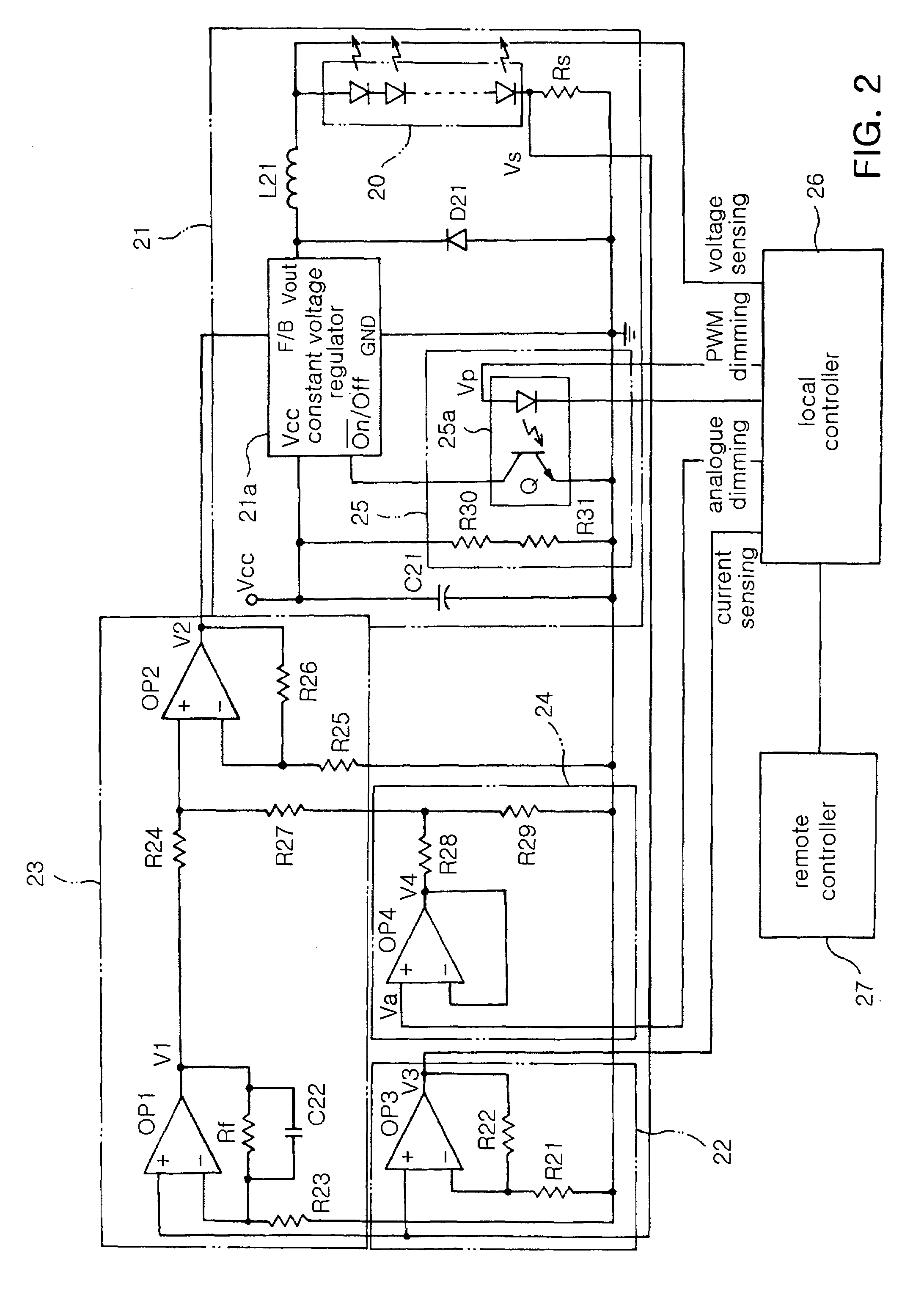
[0028]With reference to FIG. 2, an LED array driving apparatus of the present invention includes: a PWM driver 21 for providing PWM driving power to an LED array 20 with a plurality of LEDs connected in series, and for adjusting the magnitude of PWM driving power according to a feedback signal corresponding to forward driving current of the LED array 20; a current sensor 22 for detecting forward driving current running on the LED array 20 driven by the PWM driver; a feedback controller 23 for converting forward driving current running on the LED array 20 to provide to the PWM driver; an analogue dimmer 24 for regulating the feedback signal level provided by the feedback controller 23 according to an analogue dimming signal provided from outside; and a PWM dimmer 25 for regulating the duty ratio of a ...


PUM

PropertyMeasurementUnit
voltageaaaaaaaaaa
constant voltageaaaaaaaaaa
output voltageaaaaaaaaaa

Abstract

The present invention relates to an LED array driving apparatus and a backlight driving apparatus using the same which enables regulation of analogue and PWM dimming for each channel and LED of a backlight, thereby allowing uniform luminance and color in all regions of backlight. The invention converts power with a constant voltage regulator to provide PWM pulse type power to the LED array having a plurality of LEDs connected in series. It regulates the on / off interval of the constant voltage regulator via a PWM dimmer to adjust the duty ratio of the PWM pulse. Further, it regulates the level of the driving current detected at the LED array via the feedback controller and analogue dimmer to apply to the constant voltage regulator by feedback process, thus regulating the amplitude of the PWM pulse.

Description

CLAIM OF PRIORITY[0001]This application claims the benefit of Korean Patent Application No. 2005-10387 filed on Feb. 4, 2005, in the Korean Intellectual Property Office, the disclosure of which is incorporated herein by reference.BACKGROUND OF THE INVENTION[0002]1. Field of the Invention[0003]The present invention relates to an LED array driving apparatus for supplying power to drive an LED array for an LED backlight. More particularly, the present invention relates to an LED array driving apparatus and a backlight driving apparatus using the same which allows regulation of analogue and Pulse Width Modulation (PWM) dimming for each channel and LED of an LED backlight, thereby achieving uniformity of luminance and color in all regions of a backlight.[0004]2. Description of the Related Art[0005]A backlight is a device for illuminating a display panel which used to adopt Cold Cathode Fluorescent Lamp (CCFL) as a light source in the prior art. However, a Light Emitting Diode (LED) has g...

Claims


Application Information

Patent Timeline
Patent Type & Authority Patents(United States)
IPC IPC(8): H05B37/02G02F1/133G02F1/13357H01L33/00H05B41/282H05B41/392
CPCG09G3/342H05B33/0815H05B33/0863H05B33/0866H05B33/0869G09G2320/0233G09G2320/0606G09G2320/0633Y10S315/04G09G2320/064H05B45/375F16K1/2261F16K1/36F16K27/0218H05B45/20H05B45/22H05B45/24
Inventor LEE, SANG YUNGONG, JU YOUNG
Owner SAMSUNG ELECTRONICS CO LTD
Why Eureka
Try Eureka