

Angle gauge for measuring aortic sinus angle
An aortic sinus, angle technology, applied in the directions of diagnostic recording/measurement, medical science, sensors, etc., can solve problems such as non-targeting
- Summary
- Abstract
- Description
- Claims
- Application Information
AI Technical Summary
Benefits of technology
Problems solved by technology
Method used
Image

Examples
Embodiment 1
[0028] Example 1 An angle gauge for measuring the angle of the aortic sinus
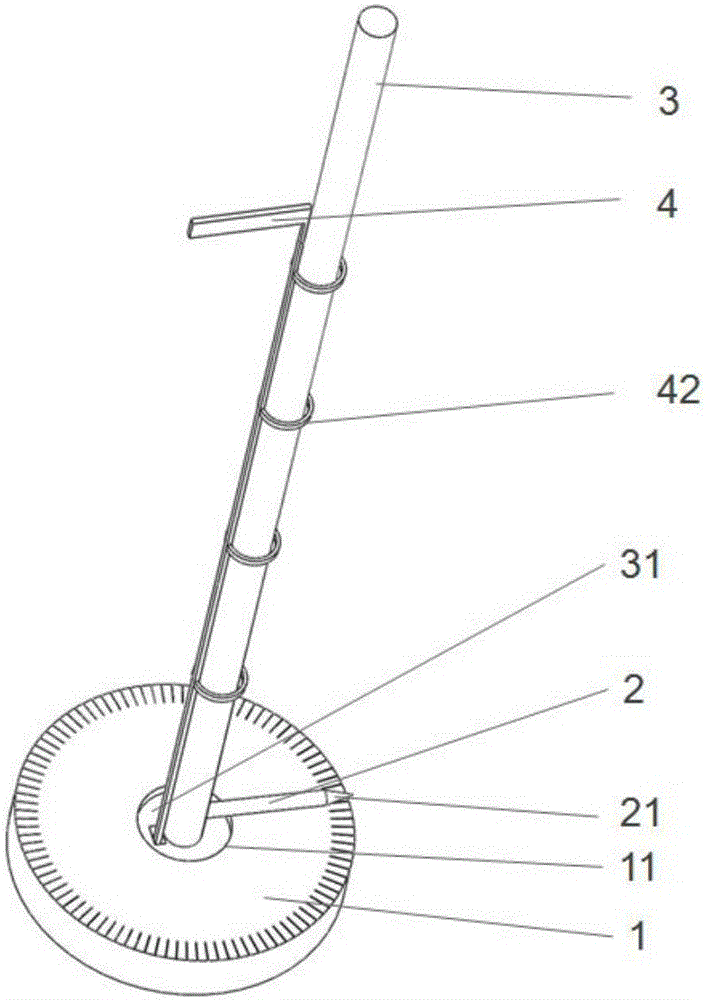
[0029] An angle gauge for measuring the angle of the aortic sinus, comprising a bottom dial 1, a rotating needle 2, and a rotating rod 3, characterized in that the rotating needle 2 is vertically connected to the rotating rod 3 and is arranged at the bottom of the rotating rod 3, and can rotate with the The rod 3 rotates; the bottom of the rotating rod 3 is vertically arranged on the dial 1, and the rotating rod 3 can drive the rotating needle 2 to rotate on the dial 1 to mark the angle to be measured. The angle gauge drives the rotating needle 2 to pass a certain angle on the dial 1 through the rotating rod 3 to measure the angle of the 360° occupied by the aortic sinus, which is accurate and fast. The bottom of the rotating rod 3 is provided with an annular protruding structure 31 , and the center of the dial 1 is provided with a hollow hole structure 11 , and the annular protruding structure 31 of...
Embodiment 2
[0030] Example 2 An angle gauge for measuring the angle of the aortic sinus
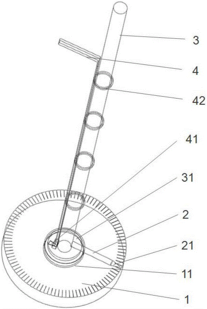
[0031] An angle gauge for measuring the angle of the aortic sinus, comprising a bottom dial 1, a rotating needle 2, and a rotating rod 3, characterized in that the rotating needle 2 is vertically connected to the rotating rod 3 and is arranged at the bottom of the rotating rod 3, and can rotate with the The rod 3 rotates; the bottom of the rotating rod 3 is vertically arranged on the dial 1, and the rotating rod 3 can drive the rotating needle 2 to rotate on the dial 1 to mark the angle to be measured. The angle gauge drives the rotating needle 2 to pass a certain angle on the dial 1 through the rotating rod 3 to measure the angle of the 360° occupied by the aortic sinus, which is accurate and fast. A locking structure 4 for fixing the rotating rod 3 after rotating to a specific position is arranged on or beside the rotating rod 3 . The setting of the clamping structure 4 can facilitate the fixing o...
Embodiment 3
[0032] Example 3 An angle gauge for measuring the angle of the aortic sinus
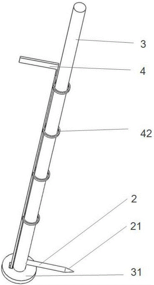
[0033]An angle gauge for measuring the angle of the aortic sinus, comprising a bottom dial 1, a rotating needle 2, and a rotating rod 3, characterized in that the rotating needle 2 is vertically connected to the rotating rod 3 and is arranged at the bottom of the rotating rod 3, and can rotate with the The rod 3 rotates; the bottom of the rotating rod 3 is vertically arranged on the dial 1, and the rotating rod 3 can drive the rotating needle 2 to rotate on the dial 1 to mark the angle to be measured. The angle gauge drives the rotating needle 2 to pass a certain angle on the dial 1 through the rotating rod 3 to measure the angle of the 360° occupied by the aortic sinus, which is accurate and fast. A locking structure 4 for fixing the rotating rod 3 after rotating to a specific position is arranged on or beside the rotating rod 3 . The setting of the clamping structure 4 can facilitate the fixing of...
PUM
 Abstract
Description
Claims
Application Information