Concentric clamping structure for cleaning brush of chemical mechanical polishing (CMP) post cleaning equipment and using method

A post-cleaning and connecting structure technology, which is applied in the field of concentric clamping structure, can solve the problems of large deviation of the concentricity of the two ends of the cleaning brush, poor cleaning and swiping effect, and complicated cleaning and swiping structure. Mode optimization, convenient concentric snap connection and quick change, compact and concise effect

Active Publication Date: 2017-04-26
北京晶亦精微科技股份有限公司
View PDF6 Cites 6 Cited by
  • Summary
  • Abstract
  • Description
  • Claims
  • Application Information

AI Technical Summary

Problems solved by technology

[0005] The present invention provides a concentric clamping structure and usage method of cleaning brushes of post-CMP cleaning equipment. It is necessary to solve the problem of complex cleaning brush clamping structure of

Method used


Image

  • Concentric clamping structure for cleaning brush of chemical mechanical polishing (CMP) post cleaning equipment and using method
  • Concentric clamping structure for cleaning brush of chemical mechanical polishing (CMP) post cleaning equipment and using method
  • Concentric clamping structure for cleaning brush of chemical mechanical polishing (CMP) post cleaning equipment and using method

Examples


Embodiment Construction

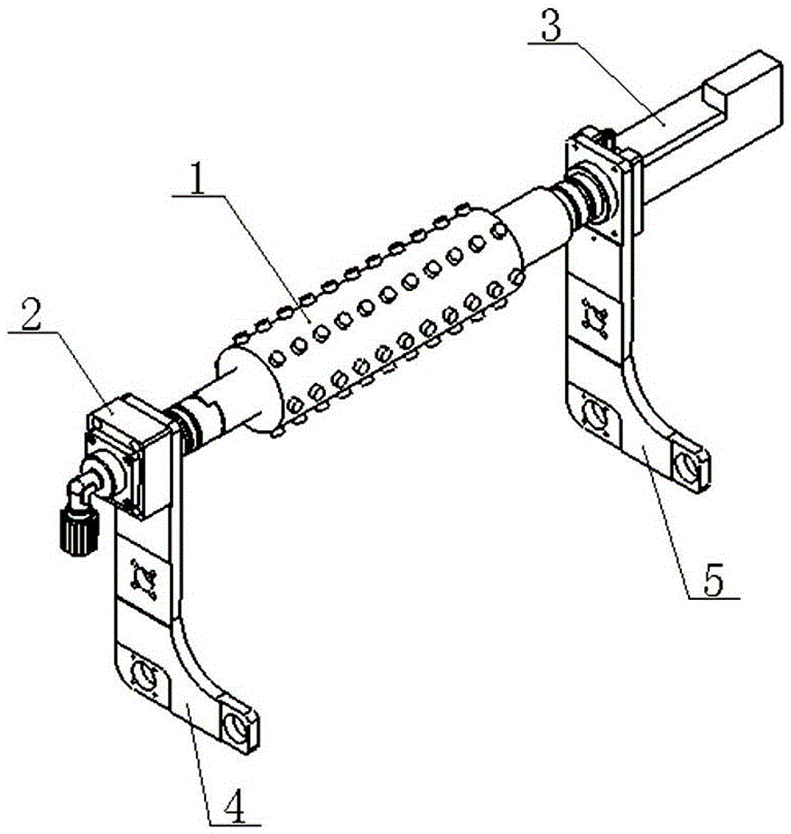
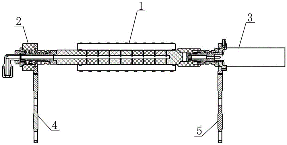
[0060] Examples see figure 1 , figure 2 As shown, the cleaning brush concentric clamping structure of this post-CMP cleaning equipment includes a cleaning brush 1, an idler shaft structure 2 that is positioned in a tapered hole with the cleaning brush 1 and transmits force in a rectangular groove, and is positioned in a tapered hole with the cleaning brush 1 and A telescopic drive shaft structure 3 with uniform force transmission in four directions, a left swing frame 4 supporting the idler shaft structure 2 and a right swing frame 5 supporting the telescopic drive shaft structure 3. The left swing frame 4 is sleeved on the cavity seat 2-3 of the idle shaft structure 2. The right swing frame 5 is sleeved on the motor seat 3-4 of the retractable drive shaft structure 3.

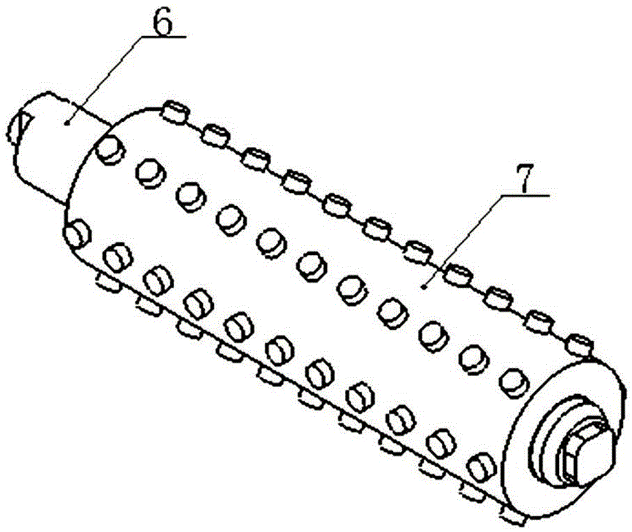
[0061] see Figure 3-5 As shown, the cleaning brush 1 includes a brush shaft 6 and a brush 7 sleeved on the brush shaft 6; the right end of the brush shaft 6 has a centering cone shaft 6.1 and a square sha...


PUM


Abstract

The invention relates to a concentric clamping structure for a cleaning brush of chemical mechanical polishing (CMP) post cleaning equipment and a using method. The concentric clamping structure comprises the cleaning brush, an idle shaft structure, a telescopic driving shaft structure, a left swing frame and a right swing frame, wherein taper hole positioning and rectangular groove force transferring are achieved between the idle shaft structure and the cleaning brush; taper hole positioning and square uniform force transferring are achieved between the telescopic driving shaft structure and the cleaning brush; the left swing frame supports the idle shaft structure; and the right swing frame supports the telescopic driving shaft structure. The cleaning brush comprises a brush shaft and a brush body arranged on the brush shaft in a sleeving mode. A centering taper shaft and a square shaft are arranged at the right end of the brush shaft and are concentric with the telescopic driving shaft structure. A positioning taper shaft and a rectangular shaft are arranged at the left end of the brush shaft and are concentric with the idle shaft structure. A purified water inlet communicating with an inner cavity of the brush shaft is formed in the center of the centering taper shaft. The concentric clamping structure is compact and simple, the clamping layout of the cleaning brush is optimized, the clamping concentricity of the cleaning brush and the sealing performance of the purified water through joint end can be effectively improved, and convenient and fast replacement is achieved.

Description

technical field [0001] The invention relates to a concentric clamping structure of a cleaning brush of cleaning equipment after CMP, and a method for using the concentric clamping structure. Background technique [0002] CMP (chemical mechanical Polishing) post-cleaning equipment is equipment for surface precision cleaning after high-precision polishing on the surface of electronic device wafers. In the post-CMP cleaning process, scrubbing with a brush combined with a spray medium is an effective way to remove contaminants on the wafer surface. [0003] At present, the overseas prototypes of post-cleaning equipment that can be seen are connected to the cleaning brush in the following way: the cleaning brush idler shaft unit and the cleaning brush drive shaft unit are superimposed as one. This clamping method results in a complex structure of the equipment and concentrated functions, especially when the two ends of the cleaning brush are docked with square positioning, resul...

Claims


Application Information

Patent Timeline
IPC IPC(8): B08B1/04B08B13/00F16C3/03
CPCB08B1/002B08B1/04B08B13/00F16C3/03
Inventor 陶利权蒲继祖史霄尹影李元升
Owner 北京晶亦精微科技股份有限公司
Why Eureka
Try Eureka