Electronic lock mechanism and unlocking method thereof

A technology of electronic locks and lock casings, which is applied in the field of locks, can solve the problems of long training period for operators, complex assembly process, and low production efficiency, and achieve the goal of improving production efficiency and good product rate, simple assembly process, and convenient processing and production Effect

Active Publication Date: 2017-04-26
GUANGDONG EDA MEDICAL TECH CO LTD
View PDF5 Cites 0 Cited by
  • Summary
  • Abstract
  • Description
  • Claims
  • Application Information

AI Technical Summary

Problems solved by technology

[0003] However, most of the lock products currently produced in the lock industry use a full mechanical mechanism to control the unlocking and locking of the lock. Due to the high precision requirements of the lock parts, the large number of parts and the complicated assembly process of this mechanical control mechanism, the production Many problems such as low production efficiency, high defect rate and high cost in the processing process; and due to the complex assembly process and long training period for operators, the effect is not good

Method used


Image

  • Electronic lock mechanism and unlocking method thereof
  • Electronic lock mechanism and unlocking method thereof
  • Electronic lock mechanism and unlocking method thereof

Examples


Embodiment

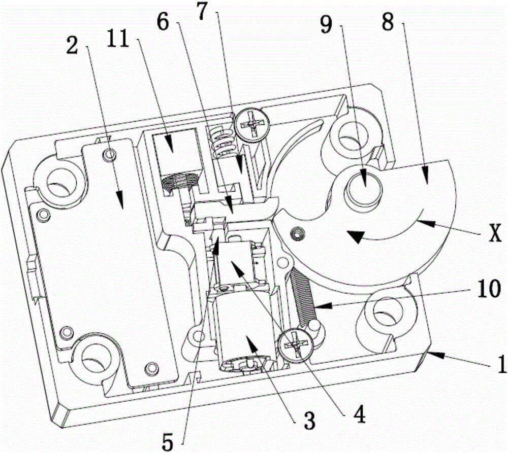
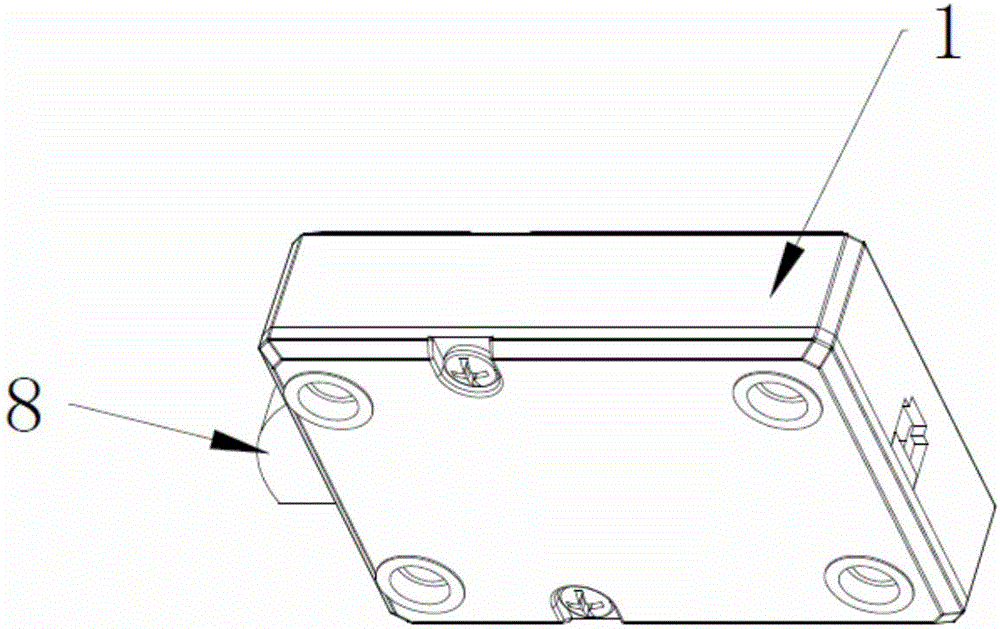
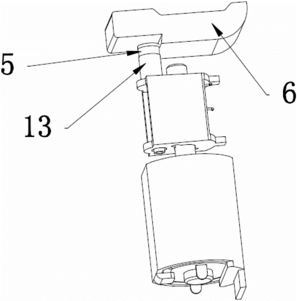
[0019] Such as figure 1 and figure 2 , the present invention provides an electronic lock mechanism, including a lock case 1 and a circuit controller 2 located in the lock case 1, a motor 3, a power conversion mechanism 4, a switch tongue 5, a transmission rod 6, an elastic tongue pressing mechanism 7 and a lock tongue 8. The circuit controller 2 is electrically connected to the motor 3, the motor 3 is fixed in the lock case 1 and its output end is connected to the switch tongue 5 through the power conversion mechanism 4, the lower left end of the transmission rod 6 is connected to the switch tongue 5, the upper right end of the transmission rod 6 abuts against the elastic tongue mechanism 7, the dead bolt 8 is fan-shaped and its fan-shaped center is connected to the lock housing 1 by rotating shaft 9, the transmission rod The right end of 6 abuts against the top corner of the arc of the lock tongue 8 to limit the movement of the lock tongue 8 . The above structure uses the ...


PUM


Abstract

The invention discloses an electronic lock mechanism. The electronic lock mechanism comprises a lock case as well as a circuit controller, a motor, a power conversion mechanism, an operating tongue, a transmission rod, an elastic tongue pressing mechanism and a lock tongue which are positioned in the lock case, wherein the circuit controller is electrically connected with the motor; the motor is fixedly arranged in the lock case, and the output end of the motor is connected with the operating tongue through the power conversion mechanism; the lower part at the left end of the transmission rod is connected with the top of the operating tongue; the upper part at the right end of the transmission rod abuts against the elastic tongue pressing mechanism; the lock tongue is in the shape of a fan, and a fan-shaped circle center of the lock tongue is rotatably connected onto the lock case through a rotary shaft; and the end part at the right end of the transmission rod abuts against a circular-arc vertex angle of the lock tongue to limit movement of the lock tongue. The invention further provides an unlocking method for the electronic lock mechanism. According to the electronic lock mechanism disclosed by the invention, the motor controls the transmission rod to unlock or lock the lock tongue, so that complexity degree of the mechanism is reduced, and therefore, an assembly process can be simplified, production efficiency is improved and the yield is increased; and meanwhile, the parts are simplified, the assembly process is simple, and the training period of an operator is short.

Description

technical field [0001] The present invention relates to the technical field of locks, and specifically refers to an electronic lock mechanism and an unlocking method thereof. Background technique [0002] As a container for people's daily storage of valuables, safes are self-evident. Therefore, safes are equipped with mechanical locks to cooperate with digital locks to achieve double security, and the requirements for mechanical locks are relatively high. A traditional safe lock includes a lock case, a lock cylinder case and a lock cylinder. The lock case is a semi-closed shell with an opening at the tail. , and then by bending the tail of the lock case inwardly toward the opening, the lock cylinder case is limited and kept in the lock case. [0003] However, most of the lock products currently produced in the lock industry use a full mechanical mechanism to control the unlocking and locking of the lock. Due to the high precision requirements of the lock parts, the large nu...

Claims


Application Information

Patent Timeline
IPC IPC(8): E05B47/00E05B15/10
CPCE05B15/10E05B47/0012E05B2047/0072
Inventor 黄伟康曾维全
Owner GUANGDONG EDA MEDICAL TECH CO LTD
Why Eureka
Try Eureka