
Automatic coupling type turning plate wind collecting assembly and device

An automatic coupling, plate type technology, applied in the direction of engines, wind power generation, wind turbines, etc., can solve the problems of backward development of vertical axis wind turbines, little power output, limited application scope, etc., to achieve automatic coupling sensitive, driving force. The effect of large and small wind resistance

Pending Publication Date: 2017-04-26
HUATIAN ENG & TECH CORP MCC
View PDF8 Cites 0 Cited by
  • Summary
  • Abstract
  • Description
  • Claims
  • Application Information

AI Technical Summary

Problems solved by technology

2. The driving force of the vertical shaft wind collection device is the difference between the force on the front of the wind cup and the force on the back, but the overall wind resistance of the impeller is the sum of the force on the front and back of the wind cup. Increasing the windward area makes the driving force and resistance synchronized increase, the overall wind resistance of the impeller increases exponentially, so increasing a large amount of wind resistance can only obtain a small amount of driving force, and the wind collection efficiency is very low
[0003] The existing technology has not solved the contradictory relationship between increasing the driving force and reducing the overall wind resistance, so its application range is restricted. At present, it is mainly used for sensing wind speed, and is rarely used for power output. The development status of vertical axis wind turbines is obviously lagging behind. horizontal axis wind turbine

Method used


Image

  • Automatic coupling type turning plate wind collecting assembly and device
  • Automatic coupling type turning plate wind collecting assembly and device
  • Automatic coupling type turning plate wind collecting assembly and device

Examples


Embodiment 1

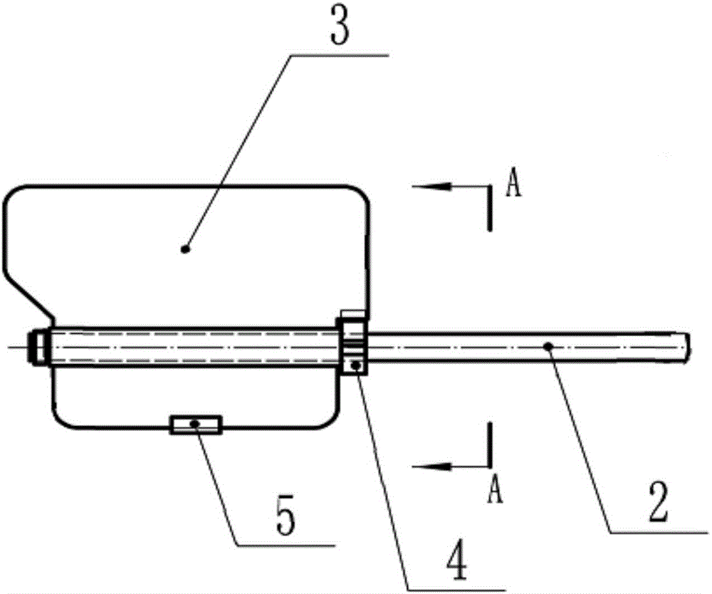
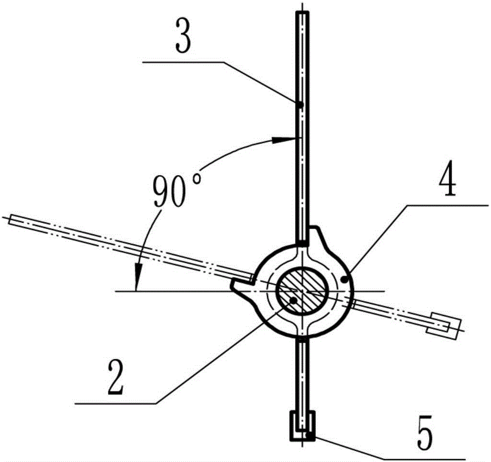
[0023] In this embodiment, an automatic coupling flip-type wind collection assembly includes a fixed rod 2, a plate-shaped blade 3 that is rotatably connected to the fixed rod 2, and a blade fixed on the fixed rod 2 for limiting the flip angle of the plate-shaped blade. Limiting device 4; the rotation axis of the plate-shaped blade 3 is coaxial with the fixed rod 2 and the center of gravity of the plate-shaped blade 3 is located on the rotation axis.

[0024] The plate-shaped blade 3 is a flat plate structure, and the plate-shaped blade 3 is divided into a first blade and a second blade relative to the axis of rotation; the area of ​​the first blade is larger than that of the second blade; the second blade is fixed A counterweight 5 is connected; the working surface of the plate-shaped blade 3 has grooves;

[0025] The blade is a plate structure, no matter it is in a vertical or tilted state, the projected area of ​​its side is very small, so when the blade rotates to the side...

Embodiment 2

[0032] Based on the above-mentioned embodiment, the limiting device 4 in this embodiment is arranged along the same direction as the plate-shaped blade 3; the limiting device 4 includes at least one stopper fixedly connected to the fixed rod 2; The rotation track of the edge of the plate-shaped blade 3 around the rotation axis intersects with the stopper;

[0033] When the wind blows to the working surface of the plate-shaped blade 3, the stopper restricts the rotation of the plate-shaped blade 3 and makes the plate-shaped blade 3 vertical to the wind direction in an upright state;

[0034] When facing the wind (blowing to the direction of the working surface), under the action of wind force, the plate-shaped blade 3 rotates around the fixed rod 2, and when it rotates to be perpendicular to the wind direction, the edge of the plate-shaped blade 3 is in contact with the barrier. Blocks are in contact with each other, the block blocks the plate-shaped blade 3 from rotating, and ...

Embodiment 3

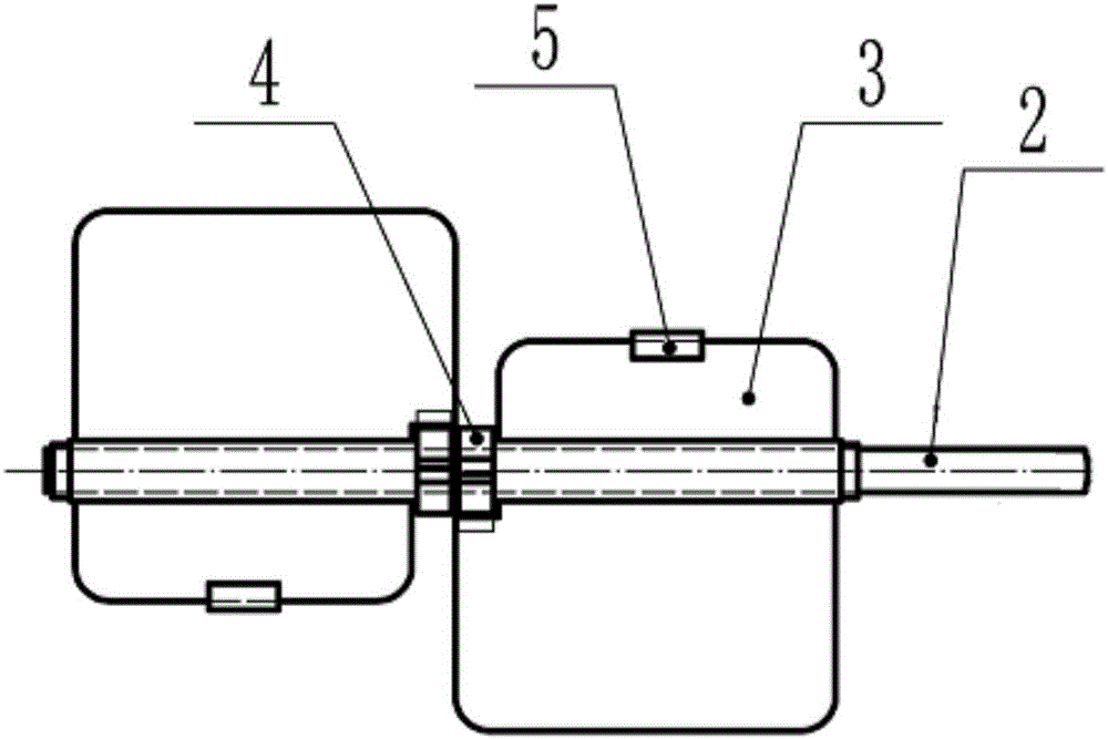
[0042] Such as image 3 As shown, based on the above-mentioned embodiment, several plate-shaped blades 3 are arranged at intervals on the fixed rod 2 in this embodiment; .

[0043] In this embodiment, a plurality of blades and a plurality of limit devices are provided, which increases the wind collection efficiency of the automatic coupling flap type wind collection assembly.


PUM


Abstract

The invention discloses an automatic coupling type turning plate wind collecting assembly. The automatic coupling type turning plate wind collecting assembly comprises a fixing rod, a plate type vane in rotary connection with the fixing rod, and a limiting device which is fixed to the fixing rod and used for limiting the rotary angle of the plate type vane, wherein the rotary axis of the plate type vane is coaxial with the fixing rod, and the gravity center of the plate type vane is located on the rotary axis. The driving force when the front side faces wind is improved through automatic turning of the vane, and the resistance when the back side faces wind is lowered, so that the key problem of a vertical shaft type wind collecting device is solved. Meanwhile, the automatic coupling type turning plate wind collecting assembly has the advantages of being large in driving force, small in wind resistance and high in wind collecting efficiency.

Description

technical field [0001] The invention relates to an automatic coupling flap type wind collecting component and device. Background technique [0002] The wind collection principle of the vertical shaft wind collection device is: select a specific geometric shape, the thrust generated by the front facing the wind is greater than the resistance formed by the back facing the wind, and the difference between the two forces is used to drive the impeller to rotate. Its typical structural type is a three-cup anemometer, and the shapes of the wind cups are mainly hemispherical and conical. The advantage of this type of structure is that the wind blowing in any wind direction can be collected, without the need for an additional pair of wind devices, and the rotation is relatively stable, but the shortcomings caused by its own structural reasons are also obvious: 1. Its front (concave) When facing the wind or the back (convex) facing the wind, the projected area remains the same, only ...

Claims


Application Information

Patent Timeline
Patent Type & Authority Applications(China)
IPC IPC(8): F03D80/00
CPCY02E10/72
Inventor 吴天福程寒飞张鑫珩王月萍
Owner HUATIAN ENG & TECH CORP MCC
Learn More