
Self-locking hydraulic cylinders via elastic elements

A technology of hydraulic cylinders and elastic parts, applied in the field of hydraulic cylinders, to avoid dents, avoid insufficient locking force, and improve stability

Active Publication Date: 2019-01-15
泸州长江液压密封件有限公司
View PDF8 Cites 0 Cited by
  • Summary
  • Abstract
  • Description
  • Claims
  • Application Information

AI Technical Summary

Problems solved by technology

Therefore, the object of the present invention is to provide a hydraulic cylinder that realizes self-locking through an elastic member, and solve the problem of how to make the hydraulic cylinder withstand external load stably for a long time without any displacement and lock the extended length of the piston rod when the movement stops.

Method used


Image

  • Self-locking hydraulic cylinders via elastic elements
  • Self-locking hydraulic cylinders via elastic elements
  • Self-locking hydraulic cylinders via elastic elements

Examples


Embodiment 1

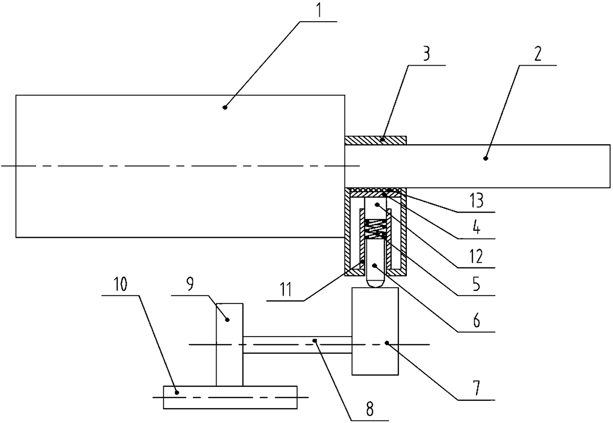
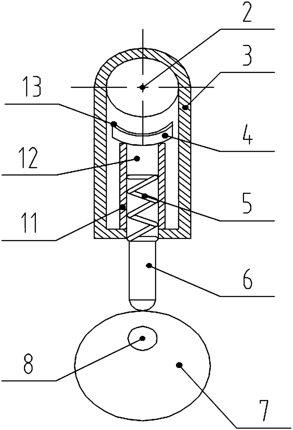
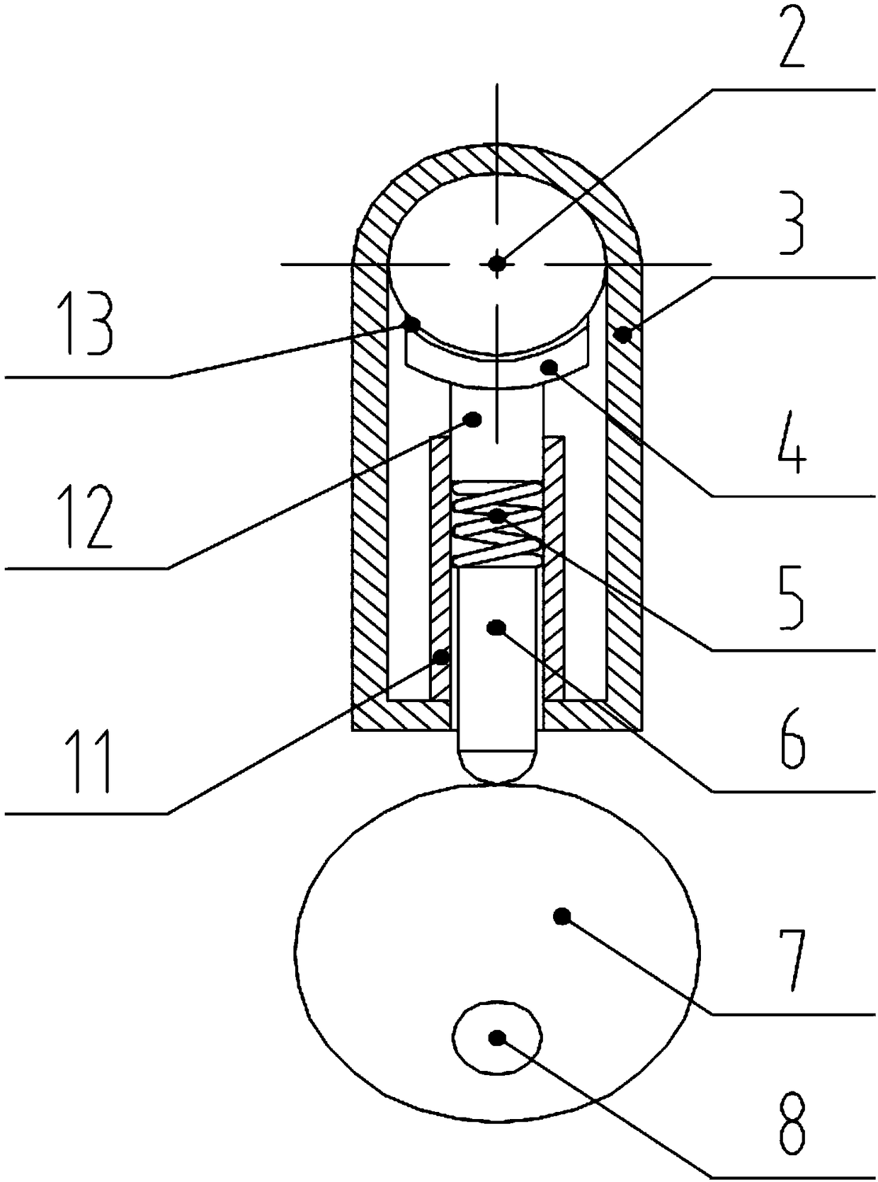
[0023] Such as Figure 1-Figure 3 As shown, the present invention realizes the self-locking hydraulic cylinder through an elastic member, including a hydraulic cylinder body 1 and a locking device arranged on the end face of the hydraulic cylinder body 1, the hydraulic cylinder body 1 is provided with a piston rod 2, and the locking The device includes a positioning frame 3, an eccentric wheel 7, a driving device, and a tightening plate 4, a spring 5, and a guide rod 6 connected in sequence. The positioning frame 3 is installed on the end face of the hydraulic cylinder body 1, and the end face is a piston rod. 2 end faces that can be freely retracted; the piston rod 2 moves through the positioning frame 3, the clamping plate 4, the spring 5 and the guide rod 6 are all located in the positioning frame 3, and the end of the guide rod 6 away from the spring 5 is connected to the eccentric wheel 7 contacts, with the rotation of the eccentric wheel 7, the pressing plate 4 can press...

Embodiment 2

[0029] This embodiment is a further description based on the first embodiment.

[0030] In the structure of the first embodiment, when the center line of the eccentric wheel 7 approaches the axis of the piston rod 2, gravity is mainly used to make the clamping plate 4, the spring 5 and the guide rod 6 fall down. When the axis of the guide rod 6 is not in the vertical direction, the speed of the clamping plate 4 leaving the piston rod 2 is relatively slow, and may even be in a position of contact with the piston rod 2 all the time, which is not convenient for the free expansion and contraction of the piston rod 2.

[0031] At this time, a rotating groove concentric with the eccentric wheel 7 can be set on the side wall of the eccentric wheel 7, the opening size of the rotating groove is smaller than the bottom size of the groove, and a The slide block matched with the cross-sectional size of the rotating groove, along with the rotation of the eccentric wheel 7, the guide rod 6 ...


PUM


Abstract

The invention discloses a hydraulic cylinder capable of realizing self-locking through an elastic part. The hydraulic cylinder comprises a hydraulic cylinder body and a locking device, wherein a piston rod is arranged in the hydraulic cylinder body; the locking device comprises a positioning frame, an eccentric wheel, a drive device as well as a tightening plate, a spring and a guide rod which are sequentially connected, wherein the positioning frame is mounted on the end surface of the hydraulic cylinder body; the piston rod movably penetrates through the positioning frame; the tightening plate, the spring and the guide rod are positioned in the positioning frame; one end, away from the spring, of the guide rod is in contact with the eccentric wheel; along with rotation of the eccentric wheel, the tightening plate can tighten the piston rod; and the drive device drives the eccentric wheel to rotate. When the distance from the center of the eccentric wheel to the axis of the piston rod is the longest, the tightening plate is away from the piston rod; and when the distance from the center of the eccentric wheel to the axis of the piston rod is gradually reduced, the tightening plate gradually tightens the piston rod under action of the spring and the guide rod, so that the piston rod is locked to a needed position.

Description

technical field [0001] The invention relates to a mechanical device, in particular to a hydraulic cylinder realizing self-locking through an elastic member. Background technique [0002] A hydraulic cylinder is a hydraulic actuator that converts hydraulic energy into mechanical energy and performs linear reciprocating motion (or swing motion). It has simple structure and reliable operation. When it is used to realize reciprocating motion, the deceleration device can be eliminated, and there is no transmission gap, and the motion is stable, so it is widely used in various mechanical hydraulic systems. The output force of the hydraulic cylinder is proportional to the effective area of ​​the piston and the pressure difference on both sides; the hydraulic cylinder is basically composed of a cylinder barrel and a cylinder head, a piston and a piston rod, a sealing device, a buffer device and an exhaust device. The hydraulic cylinder is an actuator that drives and bears a large ...

Claims


Application Information

Patent Timeline
Patent Type & Authority Patents(China)
IPC IPC(8): F15B15/26F15B15/14
CPCF15B15/1419F15B15/26
Inventor 袁祖辉何运清李代军徐华明颜新东黄俊明
Owner 泸州长江液压密封件有限公司
Learn More