Vibration device for structure collapse test
A technology of a vibration device and a driving device, which is applied in the field of civil engineering, can solve the problems of unpublished similar patent applications, no vibration excitation method, etc., and achieves the effect of simple and reliable structure and avoiding twisting.
- Summary
- Abstract
- Description
- Claims
- Application Information
AI Technical Summary
Problems solved by technology
Method used
Image
Examples
Embodiment 1
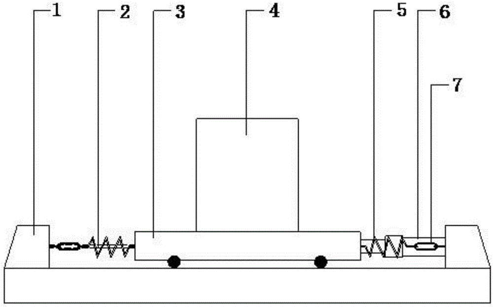
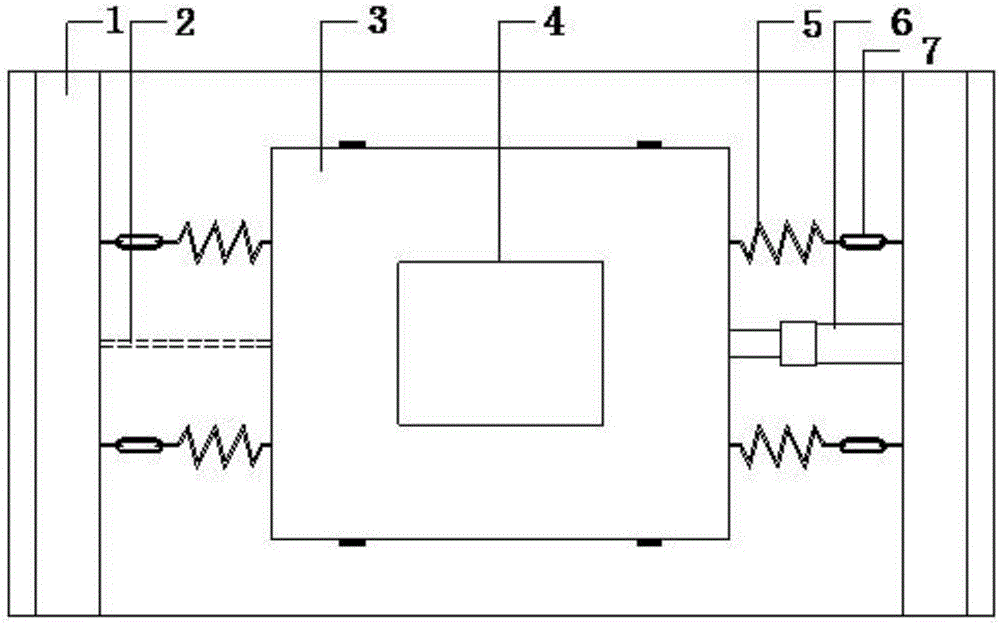
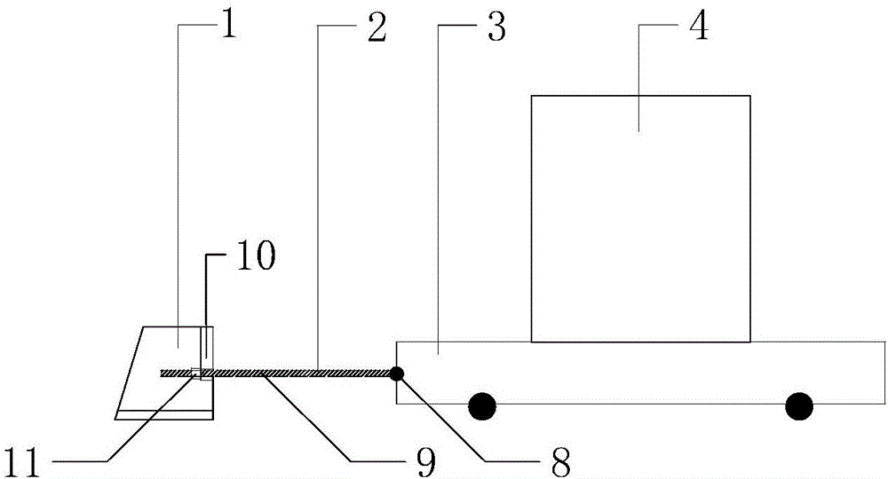
[0035] As shown in references 1 and 2, the present invention provides a vibration device for structural collapse tests, including a trolley 3, a spring set 5, a driving device 6, a limiting device 2 and a fixed pedestal 1. Among them, the trolley 3 can vibrate along the horizontal direction, and the test model 4 can be fixedly installed; The driving device includes a jack 6, which drives the trolley 3 to the set position, controls the amplitude of the test model 4, and inputs the energy required for the collapse of the structure; the limit device 2 adopts a steel wire rope that can be cut off quickly, and fixes the trolley 3 on the ground through the steel wire rope. After setting the position and cutting the wire rope, the trolley 3 vibrates horizontally under the action of the spring group 5 . According to the needs of the test, two pairs of springs of the same specification are selected in parallel to form the spring group 5, and are installed symmetrically on both sides of...
Embodiment 2
[0047] Such as figure 1 , 2 As shown, this embodiment provides a vibrating device for structural collapse test, the structure of the vibrating device is basically the same as that of Embodiment 1, the difference is that the limiting device 2 adopts a steel screw that can be quickly released and the length can be adjusted by a nut .
[0048]This embodiment also provides a method for performing a collapse test using the vibrating device in this embodiment, the method comprising the following steps:
[0049] (1) Connect the trolley 3 and the spring group 5 with the fixed pedestal 1 by using turnbuckle screws 7;
[0050] (2) Relying on the fixed pedestal 1, use the jack 6 to adjust the turnbuckle 7 so that the trolley 3 can vibrate in the horizontal direction, and the tightening distance of the turnbuckle 7 exceeds the set amplitude of the trolley;
[0051] (3) The test model 4 is fixedly installed on the dolly 3;
[0052] (4) Apply an initial displacement to the trolley 3 wit...
PUM
 Abstract
Description
Claims
Application Information
 - R&D
- Intellectual Property
- Life Sciences
- Materials
- Tech Scout
- Unparalleled Data Quality
- Higher Quality Content
- 60% Fewer Hallucinations
Browse by: Latest US Patents, China's latest patents, Technical Efficacy Thesaurus, Application Domain, Technology Topic, Popular Technical Reports.
© 2025 PatSnap. All rights reserved.Legal|Privacy policy|Modern Slavery Act Transparency Statement|Sitemap|About US| Contact US: help@patsnap.com


