
A Current Sampling Method of Inverter Circuit

A current sampling and inverter circuit technology, which is applied in the direction of measuring current/voltage, measuring electrical variables, instruments, etc., can solve the problem of forced insertion of sampling window time not reaching over-modulation, etc., and achieve accurate and stable current sampling

Active Publication Date: 2019-09-20
WOLONG ELECTRIC GRP CO LTD
View PDF7 Cites 0 Cited by
  • Summary
  • Abstract
  • Description
  • Claims
  • Application Information

AI Technical Summary

Problems solved by technology

[0009] The technical problem to be solved and the technical task proposed by the present invention are to perfect and improve the existing technical scheme, and provide a current sampling method of the inverter circuit, so as to solve the forced insertion of the sampling window in the PWM wave of the current sampling method in the prior art time without reaching the overmodulation problem for the purpose of

Method used


Image

  • A Current Sampling Method of Inverter Circuit
  • A Current Sampling Method of Inverter Circuit
  • A Current Sampling Method of Inverter Circuit

Examples


Embodiment Construction

[0025] The technical solution of the present invention will be further described in detail below in conjunction with the accompanying drawings.

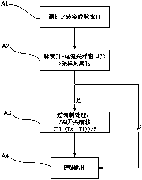
[0026] Such as figure 1 As shown, a current sampling method of an inverter circuit includes the following steps:

[0027] Step A1: When the sampling point of the phase current is sampled at the underflow point of the triangular wave, first convert the modulation ratio into pulse width T1.

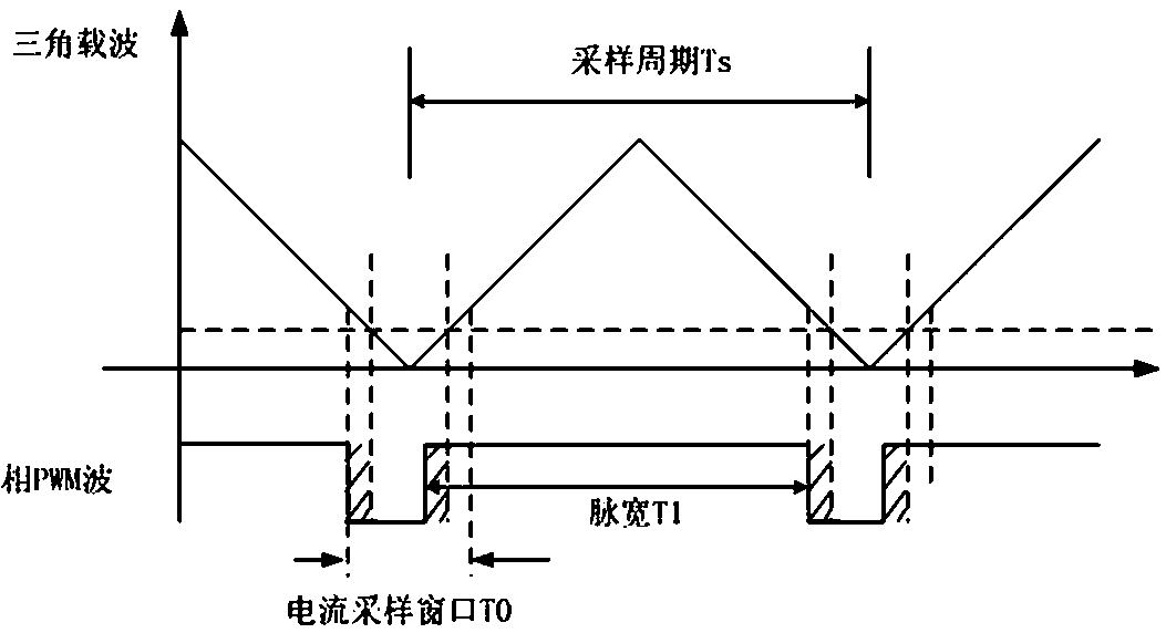
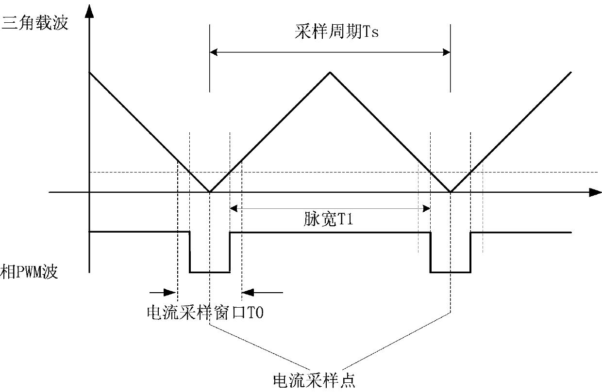
[0028] Step A2: Judgment of the overmodulation state. The method of judging the modulation state is to first calculate the sum of the pulse width of each phase and the current sampling window time, and then compare it with the sampling period TS to determine the pulse width and current sampling window time of a sampling phase. If the sum is greater than the sampling period Ts, the inverter has entered the overmodulation state; if it is judged that the sum of the pulse width of all sampling phases and the current sampling window time is less than ...


PUM


Abstract

The invention provides a current sampling method of an inverter circuit and relates to the current sampling method of the inverter circuit. In the prior art, due to the existence of the sampling window time, the voltage output usually does not realize the over-modulation or the current spike can still be sampled for current sampling during over-modulation. According to the technical scheme of the invention, the method comprises the steps of converting a modulation ratio into a pulse width T1 during the underflow point sampling process of triangular waves at the sampling points of the phase current; carrying out the over-modulation state judgment; if the current state is the over-modulation state, conducting the PWM over-modulation treatment and then performing the PWM output; otherwise, directly performing the PWM output. According to the technical scheme, the PWM modulation ratio can be improved. The problem of the current sampling method in the prior art that the sampling window time is forcibly inserted in PWM waves so as not to realize the over-modulation state can be solved.

Description

technical field [0001] The invention relates to a current sampling method of an inverter circuit. Background technique [0002] In high-performance motor control, the current loop is often the inner loop, while the speed loop, torque loop or other controls are often the outer loop. The accuracy and real-time performance of current detection are the basis for the entire control performance guarantee. [0003] In the inverter circuit, the current detection circuit can be divided into three types: [0004] The first is to directly use current sampling components such as current transformers or Hall current sensors for current sampling. This method has a simple circuit, but is expensive and bulky. [0005] The second is to connect the sampling resistor between the lower bridge arm of the power device and the ground, and obtain the current magnitude by sampling the voltage drop. Therefore, this method needs to simultaneously sample the sampling resistor when the lower bridge arm...

Claims


Application Information

Patent Timeline
Patent Type & Authority Patents(China)
IPC IPC(8): G01R19/00
Inventor 冯芬张卡飞
Owner WOLONG ELECTRIC GRP CO LTD
Learn More