An arc detection probe

A technology for detecting probes and arc light, applied in the field of light detection, can solve the problems of small detection angle range, detection accuracy and sensitivity, and achieve the effect of small intensity difference

Active Publication Date: 2019-07-05
JIANGSU ALLRAY
View PDF5 Cites 0 Cited by
  • Summary
  • Abstract
  • Description
  • Claims
  • Application Information

AI Technical Summary

Problems solved by technology

Among them, the probes are generally divided into single-point and line-type, and there are generally the following disadvantages: the single-point probe can only capture the light in a relatively small area around it, and the detection angle range is small; the line-type sensor is usually composed of a ring-shaped optical fiber, which can Collects light over a larger area along the fiber path, but with less detection accuracy and sensitivity

Method used


Image

  • An arc detection probe
  • An arc detection probe
  • An arc detection probe

Examples


Embodiment 1

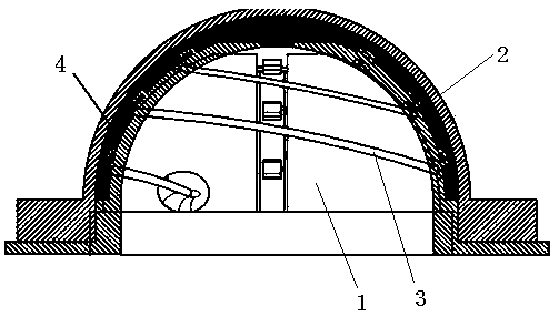
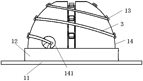
[0021] Example 1, please refer to Figure 1 to Figure 3 , an arc detection probe, including a base 1, a transparent shell 2 set outside the base 1, a fluorescent optical fiber 3 wound on the surface of the base 1, and fluorescent rubber powder 4 filled between the base 1 and the transparent shell 2, and the base 1 includes a bottom plate 11. The boss 12 on the bottom plate 11, the winding platform 14 on the boss 12, the outer contours of the bottom plate 11, the boss 12, and the winding platform 14 are all circular, and the bottom plate 11, the boss 12, and the winding platform 14 The diameter of the outer contour decreases successively. The surface of the winding table 14 is provided with a plurality of grooves 13 for fixing the fluorescent optical fiber 3 , and the surface of the winding table 14 is also provided with a fiber fixing hole 141 . The base 1 and the transparent shell 2 are connected by screws or card slots, there is a gap between the outer surface of the base 1...

Embodiment 2

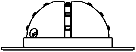
[0029] Example 2, please refer to Figure 4 , the base is a spherical shape capable of detecting 360°, and the other structures are the same as in Embodiment 1, and will not be repeated here.

[0030] A method for manufacturing an arc detection probe, comprising the following steps:

[0031] (1), choose the appropriate transparent shell;

[0032] Among them, the transparent shell should be Lambertian or conical; it can ensure the light intensity received by the probe at all angles

[0033] consistency.

[0034] (2) Design a suitable base according to the size of the transparent shell, and leave a certain distance between the outer surface of the base and the inner surface of the lens;

[0035] (3) Choose a fluorescent optical fiber of appropriate length, one end passes through and fixes in the fiber fixing hole of the base, then wraps it tightly along the groove on the surface of the base and fixes it on the base, and the other end of the optical fiber passes through the li...


PUM


Abstract

The present invention a light arc detection probe which comprises a base, a transparent shell which sleeves the base, a fluorescence fiber wound around the surface of the base, and fluorescent powder put between the base and the transparent shell. The surface of the base is provided with a plurality of multiple grooves for fixing the fluorescence fiber. The surface of the base is also provided with fiber fixing holes. Compared with present single point and line type probes, a full angle range of 180 degrees or 360 degrees can be detected and is much larger than that of the single point probe, and the detection precision and received light intensity are much larger that of the line type probe. Moreover, under the same incident light, the intensity difference of received light within a detection range is small.

Description

technical field [0001] The invention relates to the field of light detection, in particular to an arc detection probe. Background technique [0002] The power system can cause arc light due to various short-circuit reasons. In order to detect the arc light in time and cut off the arc light safely and quickly, some manufacturers have introduced an arc light detection system that uses optical fiber to transmit signals. The optical fiber transmission signal can not only reduce the response time of the detection system, but also avoid electromagnetic interference and improve the reliability of the system. [0003] At present, the arc detection system for optical fiber transmission signal is mainly composed of probe, transmission optical fiber and photoelectric module. Among them, the probes are generally divided into single-point and line-type, and there are generally the following disadvantages: the single-point probe can only capture the light in a relatively small area aroun...

Claims


Application Information

Patent Timeline
Patent Type & Authority Patents(China)
IPC IPC(8): G01R31/12
CPCG01R31/1218
Inventor 胡天邦
Owner JIANGSU ALLRAY
Why Eureka
Try Eureka