Detection device

a detection device and detection technology, applied in the direction of measurement devices, instruments, using reradiation, etc., to achieve the effect of more accurate detection of interferen

Active Publication Date: 2016-06-14
FURUNO ELECTRIC CO LTD
View PDF9 Cites 0 Cited by
  • Summary
  • Abstract
  • Description
  • Claims
  • Application Information

AI Technical Summary

Benefits of technology

[0006]Thus, the present invention is made in view of the above situations, and provides a detection device that can detect interference more accurately comparing to the conventional device without performing the interference removal more than needed.
[0008]Thereby, the detection device of this aspect determines that the reception signal is interference only when the intensity difference is continuously large (the threshold or larger) for over the reference time period. For example, in a fish finder, interference is determined only when an area of the reception signal with the large intensity difference has some extent of continuity in the depth direction. Therefore, an erroneous determination of interference in the reception signal is prevented when, for example, the echoes in the current measurement and the previous measurement from the same target object are detected at depths far apart from each other.
[0012]For example, when the interference signals accidentally overlap with each other at the same depth in the reception signals, it is not detected as the interference in one time detection processing because the intensity difference between the interference signals is small. Therefore, by repeating the interference detection processing for the data after the interference removal, the accuracy can be improved. Note that, the interference detection is performed by, for example, outputting the previous reception signal without using the current reception signal, or, when the processing is not performed in real time (e.g., when the processing is performed after the reception signals for a plurality of extra measurements is accumulated), a value averaged by using the previous echo data and the next is outputted. By keeping the outputted value in a memory for a moment and repeatedly detecting interference, the interference detection can more accurately be performed.

Problems solved by technology

However, because the method disclosed in JP2003-322678A determines as interference as long as the intensity difference is large, there is a possibility that a reception signal that is a normal echo of other than interference (a target object such as fish) may be determined as interference.

Method used


Image

  • Detection device
  • Detection device
  • Detection device

Examples


Embodiment Construction

[0028]Next, an embodiment of the present invention is described with reference to the appended drawings.

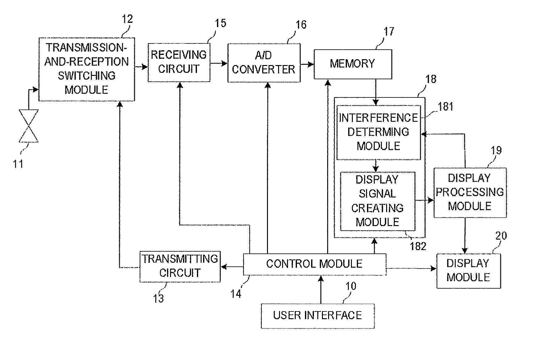
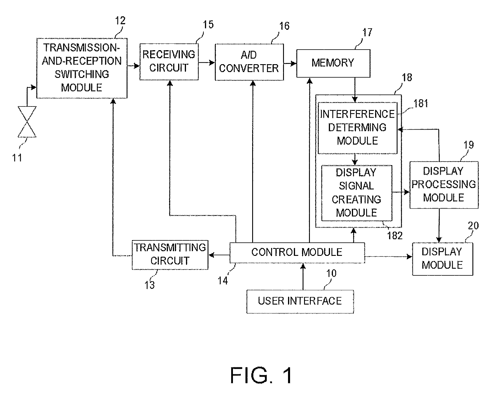
[0029]FIG. 1 is a block diagram showing a configuration of a detection device utilized as a fish finder in this embodiment. The fish finder includes a user interface 10, a transducer 11, a transmission-and-reception switching module 12, a transmitting circuit 13, a control module 14, a receiving circuit 15, an A / D converter 16, a memory 17, a signal processing module 18, a display processing module 19, and a display module 20.

[0030]The control module 14 entirely controls the fish finder. The control module 14 receives an instruction input, such as setting a detecting range, from the user interface 10. The control module 14 responds to the input to set a transmitting period from the transmitting circuit 13 and the detecting range, set a corresponding period of a sampling pulse toward a A / D converter 16, generate write and read clocks and address for the memory 17, generate various ...


PUM


Abstract

This disclosure provides a detection device, which includes a transceiving module for transmitting a transmission signal and receiving an echo caused by the transmission signal to output a reception signal according to an intensity of the echo, a memory module for storing the reception signals for a plurality of measurements, and an interference detecting module for detecting an interference signal from the reception signals, the interference detecting module determining that the reception signal contains the interference signal when the reception signal has an intensity difference with the previous reception signal by more than a predetermined threshold for over a reference time period in one measurement.

Description

CROSS-REFERENCE TO RELATED APPLICATION(S)[0001]The application claims priority under 35 U.S.C. §119 to Japanese Patent Application No. 2010-106103, which was filed on May 6, 2010 the entire disclosure of which is hereby incorporated by reference.TECHNICAL FIELD[0002]The present invention relates to a device for transmitting and receiving a sound and / or an electromagnetic wave, and particularly relates to a detection device for detecting an echo and interference.BACKGROUND OF THE INVENTION[0003]Conventionally, devices, such as radar apparatuses and fish finders, for transmitting and receiving a sound and / or an electromagnetic wave perform various kinds of processing to remove interference caused by another device(s). For example, JP2003-322678A discloses a method that is performed in the fish finder, in which interference is detected based on whether a ratio of an amplitude of a reception signal from a measurement (current measurement) and an amplitude of a reception signal from a pr...

Claims


Application Information

Patent Timeline
Patent Type & Authority Patents(United States)
IPC IPC(8): G01S15/00G01S7/62G01S7/527G01S15/96G01S7/292
CPCG01S7/2927G01S7/527G01S7/6218G01S15/96
Inventor ONISHI, YURIKOMISONOO, SATOSHI
Owner FURUNO ELECTRIC CO LTD
Why Eureka
Try Eureka