IGBT fault monitoring device and method

A technology for monitoring devices and faults, which is applied in the direction of measuring devices, measuring electricity, and measuring electrical variables, etc. It can solve the problems of consuming maintenance costs and ignoring the impact, and achieve the effect of avoiding blind replacement and saving maintenance costs

Active Publication Date: 2017-04-26
SHANDONG UNIV OF SCI & TECH
View PDF5 Cites 8 Cited by
  • Summary
  • Abstract
  • Description
  • Claims
  • Application Information

AI Technical Summary

Problems solved by technology

Once a fault is detected, it will be treated as a permanent fault without analysis, which will cost a lot of maintenance costs
[0003] At present, the research on IGBT at home and abroad mainly focuses on performance testing and detection of permanent faults, ignoring the impact of intermittent faults on IGBTs

Method used


Image

  • IGBT fault monitoring device and method
  • IGBT fault monitoring device and method
  • IGBT fault monitoring device and method

Examples


Embodiment 1

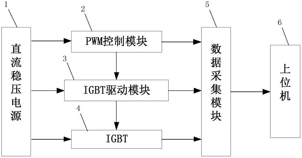
[0034] combine figure 1 As shown, an IGBT fault monitoring device includes a DC stabilized power supply 1 , a PWM control module 2 , an IGBT drive module 3 , an IGBT4 , a data acquisition module 5 and a host computer 6 .

[0035] Among them, the PWM control module 2 is used to generate pulses with adjustable frequency and amplitude, wherein one pulse signal is sent to the data acquisition module 5 , and the other pulse signal is sent to the IGBT drive module 3 .

[0036] The IGBT drive module 3 is used to amplify the received pulse signal, wherein one amplified pulse signal is sent to the data acquisition module 5, and the other amplified pulse signal is sent to the gate of the IGBT4.

[0037] The IGBT4 is used to turn on and off repeatedly under the action of the IGBT driving module 3 and generate an on-off signal, and the generated on-off signal is sent to the data acquisition module 5 through the emitter of the IGBT4.

[0038] The data collection module 5 is used for uploa...

Embodiment 2

[0043] In Embodiment 2, a monitoring method for IGBT failure is proposed, and the monitoring device used includes a DC stabilized power supply, a PWM control module, an IGBT drive module, an IGBT, a data acquisition module and a host computer.

[0044] A monitoring method for IGBT faults, comprising the steps of:

[0045] ① Pulses with adjustable frequency and amplitude are generated by the PWM control module 2, wherein one pulse signal is sent to the data acquisition module 5, and the other pulse signal is sent to the IGBT drive module 3;

[0046] ② The IGBT drive module 3 amplifies the received pulse signal, wherein the amplified pulse signal is sent to the data acquisition module 5, and the amplified pulse signal is sent to the IGBT4 gate;

[0047] ③ IGBT4 is repeatedly turned on and off under the action of IGBT drive module 3 and generates an on-off signal, which is sent to the data acquisition module through the emitter of IGBT4;

[0048] ④The data acquisition module 5 u...

Embodiment 3

[0058] This embodiment 3 proposes an analysis method for an IGBT failure, which is based on the device for an IGBT failure in the above-mentioned embodiment 1, which includes the following steps:

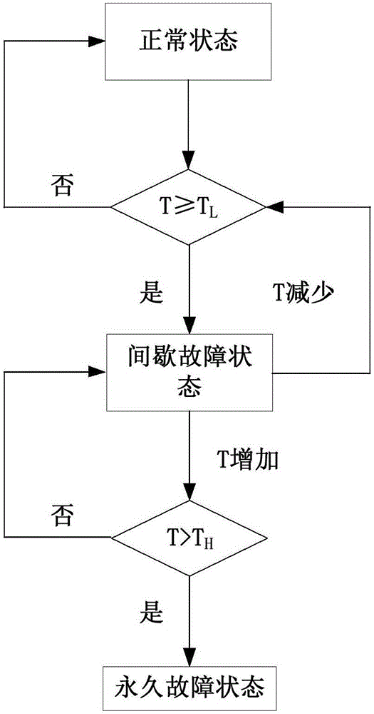
[0059] a Divide IGBT4 into normal state, intermittent fault state and permanent fault state, and establish the logical relationship of the three states, such as figure 2 shown; where: the failure rate of IGBT4 is set to T, and the threshold for IGBT4 to change from normal state to intermittent fault state is T L , the threshold for IGBT4 to change from intermittent fault state to permanent fault state is T H .

[0060] The number of IGBT4 failures will increase as the working time increases. When the failure rate T increases to T L After that, IGBT4 will enter the intermittent fault state, and the increase in the number of intermittent faults will cause cumulative damage to the structure of IGBT4, resulting in an increase in the fault frequency of IGBT4, and T will continue to in...


PUM


Abstract

The invention discloses an IGBT fault monitoring device and method. The device comprises a DC voltage-stabilizing power supply, a PWM control module, an IGBT drive module, an IGBT, a data collection module, and an upper computer. The reasonable design of connection relation among all parts of the monitoring device and a signal flowing direction facilitates the achieving of a purpose that the monitoring device carries out the fault monitoring of the IGBT. In addition, the upper computer can record the number of fault times of the IGBT, takes the fault rate as the basis, and judges what working state the IGBT is located. When the IGBT is in an intermittent fault state, the monitoring device just gives a fault alarm. When the IGBT is in a permanent fault state, the monitoring device carries out the service life warning, and reminds the replacing of the IGBT. The device and method can effectively monitor the fault type of the IGBT, reveal the relation between an intermittent fault accumulative effect and a permanent fault, predict the happening of the permanent fault, determine an optimal replacement moment for a maintainer, avoid aimless replacement, and save the maintenance cost.

Description

technical field [0001] The invention relates to an IGBT fault monitoring device and method. Background technique [0002] The application of power semiconductor devices, especially IGBTs, is the basis of many industrial systems. In some applications, IGBT modules are prone to failure due to corrosion, pollution, overheating, overload and other factors. Once a failure occurs, the usual measures are to repair or replace the failed IGBT module. In fact, intermittent failures account for 90% of all possible failures. Intermittent failure is a type of failure that lasts for a short time, recurs, and disappears without treatment. Once a fault is detected, it will be treated as a permanent fault without analysis, which will cost a lot of maintenance costs. [0003] At present, the research on IGBT at home and abroad mainly focuses on performance testing and detection of permanent faults, ignoring the impact of intermittent faults on IGBTs. Therefore, it is necessary to seek a d...

Claims


Application Information

Patent Timeline
Patent Type & Authority Applications(China)
IPC IPC(8): G01R31/26
CPCG01R31/2637
Inventor 程学珍张同轻张姣于永进许传诺尹唱唱杨婕
Owner SHANDONG UNIV OF SCI & TECH
Why Eureka
Try Eureka