
Monitoring system

A monitoring system and relationship technology, applied in transmission systems, digital transmission systems, closed-circuit television systems, etc., can solve the problem of difficult camera configuration, and achieve the effect of low configuration difficulty and ease of use.

Inactive Publication Date: 2017-04-26
SHENZHEN IPANEL TECH LTD
View PDF5 Cites 6 Cited by
  • Summary
  • Abstract
  • Description
  • Claims
  • Application Information

AI Technical Summary

Problems solved by technology

[0004] However, the process of matching the camera with the computer in this monitoring system needs to be realized through professional software. For ordinary users, it is difficult to configure the camera. When adding a new camera, the user also needs to hire a professional technician. configure

Method used


Image

  • Monitoring system
  • Monitoring system

Examples


Embodiment Construction

[0024] The following will clearly and completely describe the technical solutions in the embodiments of the present invention with reference to the accompanying drawings in the embodiments of the present invention. Obviously, the described embodiments are only some, not all, embodiments of the present invention. Based on the embodiments of the present invention, all other embodiments obtained by persons of ordinary skill in the art without making creative efforts belong to the protection scope of the present invention.

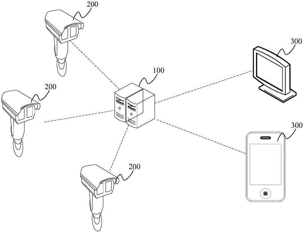
[0025] The embodiment of the present application provides a monitoring system, such as figure 1 As shown, it includes: a server 100, at least one camera 200 and at least one terminal 300, wherein,

[0026] The terminal 300 is used to send registration information or query information to the server 100, and is used to display after receiving the shooting picture of the target camera 200 sent by the server 100;

[0027] The server 100 is configured to generate ...


PUM


Abstract

The application discloses a monitoring system. When the monitoring system is utilized to configure a camera, a user only needs to send registration information containing a corresponding relationship between user information and the camera to a server through a terminal, a permission relationship between the user information and the camera is generated and stored according to the corresponding relationship between user information and the camera contained in the registration information after the server receives the registration information, and then camera configuration is completed. After the camera configuration is finished, the user can send query information through the terminal to obtain shooting images of a target camera so as to monitor the shooting images of the target camera in real time. It is less difficult to configure the camera of the monitoring system, and it is less difficult for the user to use. Moreover, the user can check monitoring situations anytime and anywhere in different forms through the monitoring system. Furthermore, videos obtained by the monitoring system can be stored in a network hard disk, and requirements of equipment used by the user are not strict.

Description

technical field [0001] The present application relates to the technical field of monitoring, and more specifically, to a monitoring system. Background technique [0002] Monitoring technology is one of the main technologies to meet people's safety needs. Electronic monitoring technology can use a large number of electronic equipment to replace managers and appliances to achieve the purpose of monitoring, greatly reducing the input of manpower and financial resources, improving monitoring efficiency and optimizing monitoring. Effect. At the same time, it also has the advantages of long data recording time and the ability to repeatedly retrieve and use monitoring data. Therefore, the monitoring system based on electronic monitoring technology has become an indispensable tool in the modern management system of various places. [0003] The monitoring system in the prior art usually includes a computer and at least one camera. By installing software in the computer and configuri...

Claims


Application Information

Patent Timeline
Patent Type & Authority Applications(China)
IPC IPC(8): H04N7/18H04N5/781H04L12/24
CPCH04N7/188H04L41/0803H04N5/781
Inventor 徐佳宏何小芬陈恋
Owner SHENZHEN IPANEL TECH LTD
Learn More