Denture scanning positioning fixture
A technology of scanning positioning and fixtures, which is applied in the field of denture scanning, can solve the problems of low precision of denture scanning three-dimensional models, inconvenient operation of denture scanning positioning and clamping, and achieve the effect of facilitating denture scanning positioning and clamping operations and improving accuracy
- Summary
- Abstract
- Description
- Claims
- Application Information
AI Technical Summary
Problems solved by technology
Method used
Image

Examples
Embodiment 1
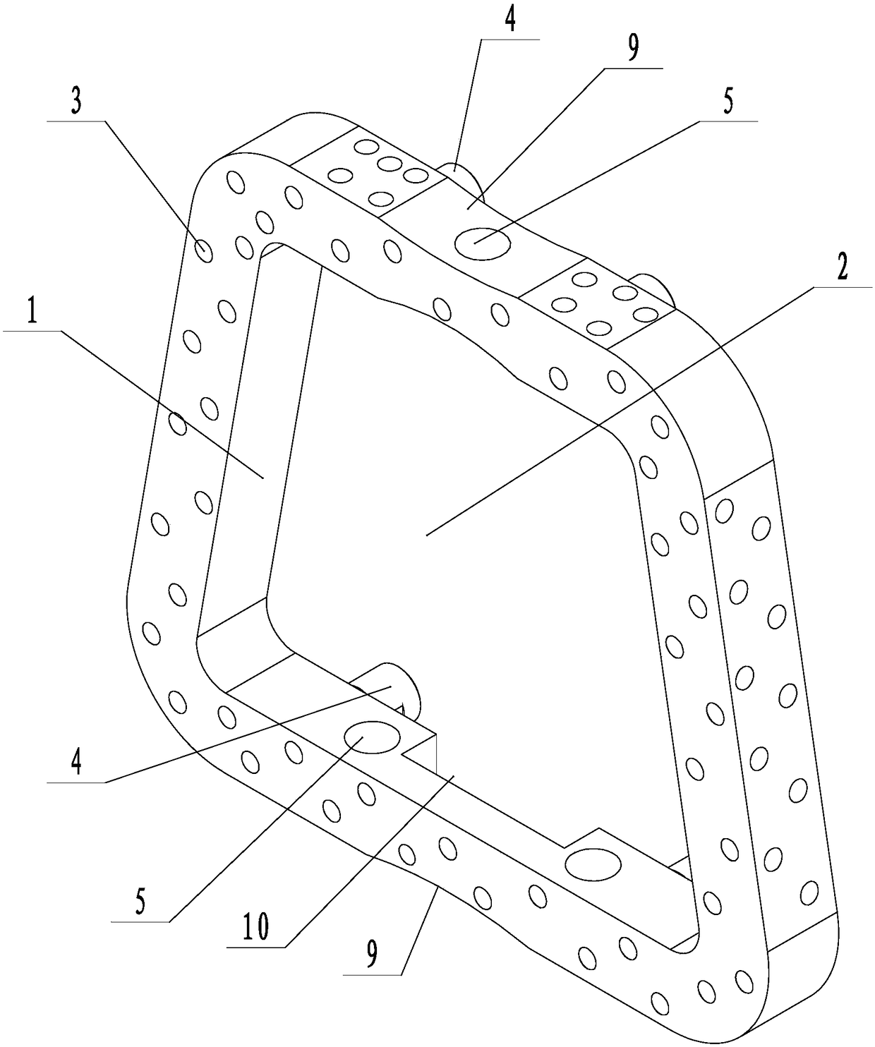
[0027] Example 1: A denture scanning positioning fixture (see attached figure 1 , Attached figure 2 ), including the marking point frame 1. The marking point frame is an isosceles trapezoidal frame structure, and the clamping cavity 2 is formed in the marking point frame. The upper surface and the four outer sides of the marking point frame are provided with several marks for scanning splicing and positioning Point 3. The marking point can be convex or concave. Four connecting columns 4 are arranged on the lower surface of the marking point frame, and two connecting columns are arranged at the upper and lower bottom edges of the marking point frame of the isosceles trapezoidal frame structure. The two opposite sides of the marking point frame are provided with clamping holes 5 that penetrate into the clamping cavity. One clamping hole is arranged on one side of the upper bottom side of the isosceles trapezoidal marking point frame with a smaller width, and two clamping holes a...
Embodiment 2
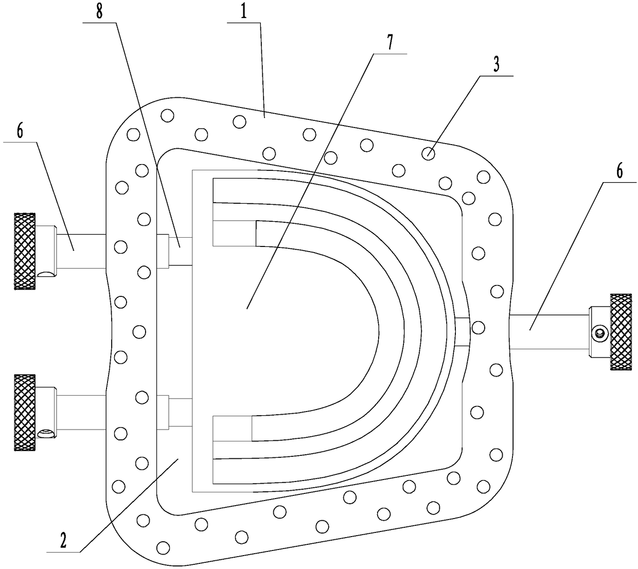
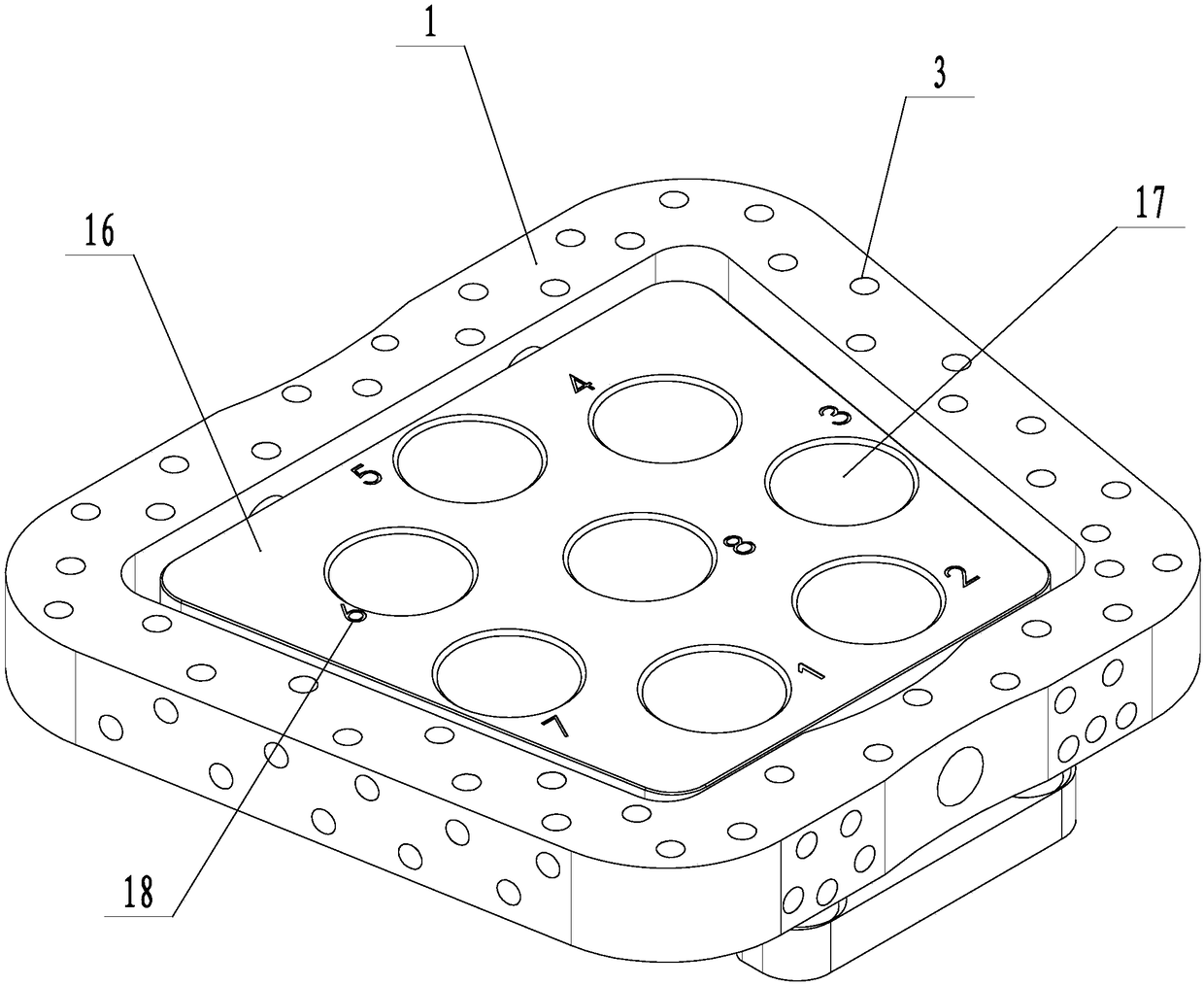
[0029] Example 2: A scanning positioning fixture for dentures (see attached image 3 , Attached Figure 4 , Attached Figure 5 ), including the mark point frame, the mark point frame is an isosceles trapezoidal frame structure, the mark point frame constitutes a clamping cavity, the upper surface of the mark point frame and the four outer sides are provided with several marking points for scanning splicing and positioning, The marking point can be a convex point or a concave point. Four connecting uprights are arranged on the lower surface of the marking point frame, and two connecting uprights are arranged at the upper and lower bottom edges of the marking point frame of the isosceles trapezoidal frame structure. The two opposite sides of the mark point frame are provided with clamping holes that penetrate the clamping cavity. One clamping hole is arranged on one side of the upper bottom side of the isosceles trapezoidal marking point frame with a smaller width, and two clampi...
Embodiment 3
[0032] Example 3: A scanning positioning fixture for dentures (see attached image 3 , Attached Figure 4 , Attached Figure 5 ), including the mark point frame, the mark point frame is an isosceles trapezoidal frame structure, the mark point frame constitutes a clamping cavity, the upper surface of the mark point frame and the four outer sides are provided with several marking points for scanning splicing and positioning, The marking point can be a convex point or a concave point. Four connecting uprights are arranged on the lower surface of the marking point frame, and two connecting uprights are arranged at the upper and lower bottom edges of the marking point frame of the isosceles trapezoidal frame structure. The two opposite sides of the mark point frame are provided with clamping holes that penetrate the clamping cavity. One clamping hole is arranged on one side of the upper bottom side of the isosceles trapezoidal marking point frame with a smaller width, and two clampi...
PUM
 Abstract
Description
Claims
Application Information
 - R&D
- Intellectual Property
- Life Sciences
- Materials
- Tech Scout
- Unparalleled Data Quality
- Higher Quality Content
- 60% Fewer Hallucinations
Browse by: Latest US Patents, China's latest patents, Technical Efficacy Thesaurus, Application Domain, Technology Topic, Popular Technical Reports.
© 2025 PatSnap. All rights reserved.Legal|Privacy policy|Modern Slavery Act Transparency Statement|Sitemap|About US| Contact US: help@patsnap.com