
Cover plate coloring method and mobile terminal

A mobile terminal and cover technology, applied in printing, printing devices, devices for coating liquid on the surface, etc., can solve problems such as air bubbles, bottom penetration, and wrinkles in the arc area of ​​the cover

Inactive Publication Date: 2017-05-10
VIVO MOBILE COMM CO LTD
View PDF1 Cites 6 Cited by
  • Summary
  • Abstract
  • Description
  • Claims
  • Application Information

AI Technical Summary

Problems solved by technology

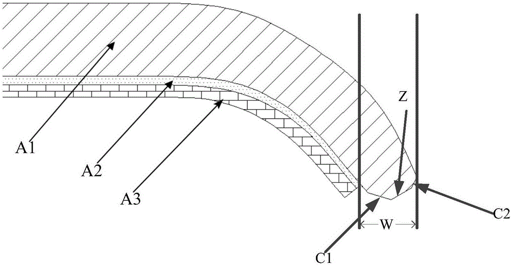
[0004] The embodiment of the present invention provides a cover coloring method to solve the problems of air bubbles, wrinkles and bottom penetration in the arc surface area of ​​the cover when using PET film to color the cover in the prior art

Method used


Image

  • Cover plate coloring method and mobile terminal
  • Cover plate coloring method and mobile terminal
  • Cover plate coloring method and mobile terminal

Examples


Embodiment 1

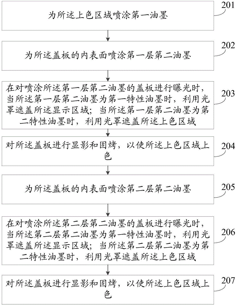
[0016] refer to figure 2 , which shows a flow chart of the steps of an embodiment of a method for coloring a cover plate according to an embodiment of the present invention, and the specific steps include:

[0017] Step 201, spraying a first ink on the colored area.

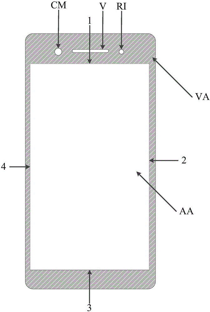
[0018] The embodiment of the present invention is applied to a 3D curved cover plate of a mobile terminal, and the cover plate includes two areas: a display area and a colored area; the display area is a touch area displayed on the cover plate and the mobile terminal The corresponding area; the colored area is the area on the cover except the display area, refer to image 3 , image 3 A schematic diagram of a cover surface of the present invention is shown; image 3 AA in is the display area, and VA is the colored area. In addition, the 3D curved cover plate may include 2 curved surfaces or 4 curved surfaces; the curved surfaces all belong to the colored area of ​​the cover plate; since this step is the colo...

Embodiment 2

[0030] refer to Figure 4 , which shows a flow chart of the steps of another embodiment of the cover coloring method according to the embodiment of the present invention, and the specific steps include:

[0031] Step 401 , spraying black photoresist ink with a preset width on the junction of the display area and the colored area.

[0032] Step 402 , exposing, developing and curing the cover plate.

[0033] Because when other layers of the screen of the mobile terminal are bonded to the cover plate, certain errors will occur; in order to reduce the impact of the error on the user’s vision during the bonding, the coloring area of ​​the cover plate can be Before coloring, after cleaning the cover plate, spray black photoresist ink with a preset width at the junction of the display area and the coloring area; wherein, refer to image 3 , the connection between the display area and the colored area includes four places: the edge of the display area pointed to by 1, 2, 3, and 4; t...


PUM


Abstract

The embodiment of the invention provides a cover plate coloring method and a mobile terminal. The coloring method is applied to a 3D cambered surface cover plate of the mobile terminal. The inner surface of the cover plate comprises a display area and a coloring area. The coloring method comprises the steps that first printing ink is sprayed onto the coloring area; second printing ink is sprayed onto the inner surface of the cover plate, and the second printing ink is photosensitive printing ink and comprises a first layer of photosensitive printing ink and a second layer of photosensitive printing ink; when the cover plate coated with the second printing ink is exposed and the second printing ink is first characteristic printing ink, the display area is covered with a photomask; when the second printing ink is second characteristic printing ink, the coloring area is covered with the photomask; and the cover plate is subjected to developing and solidification roasting, so that the coloring area is colored. According to the embodiment of the invention, through the method that the printing ink is sprayed onto the cover plate, the edge of a 3D cambered surface is free of phenomena of bottom permeating, folds and bubbles, accordingly, the aesthetic property of the 3D cambered surface cover plate on the mobile terminal is greatly improved, and the user experience is improved.

Description

technical field [0001] The invention relates to the technical field of terminals, in particular to a cover coloring method and a mobile terminal. Background technique [0002] With the popularization of mobile terminals and the continuous advancement of electronic technology, users have higher and higher requirements for the appearance of mobile terminals. Therefore, the cover of the mobile terminal touch screen has developed from the original 2D curved surface or 2.5D curved surface to a 3D curved surface. Curved surface: Compared with mobile terminals with 2D curved surface or 2.5D curved surface cover, mobile terminals with 3D curved surface cover (including 2-sided curved and 4-sided curved) have a more beautiful appearance and feel better. [0003] At present, 2D and 2.5D arc cover plates are colored by ink printing. However, since the 3D curved cover is bent on two or four sides, the ink printing method is obviously no longer applicable. Therefore, in the prior art, h...

Claims


Application Information

Patent Timeline
IPC IPC(8): B05D7/00B05D7/24B05D1/32B41M1/12
CPCB05D7/00B05D1/322B05D7/24B41M1/12
Inventor 袁小民张世强
Owner VIVO MOBILE COMM CO LTD
Learn More