Method for milling fairways and chamfers of cage bell shells

A bell-shaped shell and fairway technology, which is applied in the field of machinery, can solve the problems of wasting manpower and financial costs, and achieve the effects of preventing dust falling, convenient installation, and easy control of the rotation angle

Active Publication Date: 2018-09-21
安徽晶隆汽车工业有限公司
View PDF6 Cites 0 Cited by
  • Summary
  • Abstract
  • Description
  • Claims
  • Application Information

AI Technical Summary

Problems solved by technology

[0005] The technical problem to be solved by the present invention is that two kinds of tooling are needed for ball cage bell-shaped shell milling and chamfering, which wastes manpower and financial resources. Therefore, a method for ball cage bell-shaped shell ball lane and chamfering is provided here.

Method used


Image

  • Method for milling fairways and chamfers of cage bell shells
  • Method for milling fairways and chamfers of cage bell shells
  • Method for milling fairways and chamfers of cage bell shells

Examples


Embodiment 1

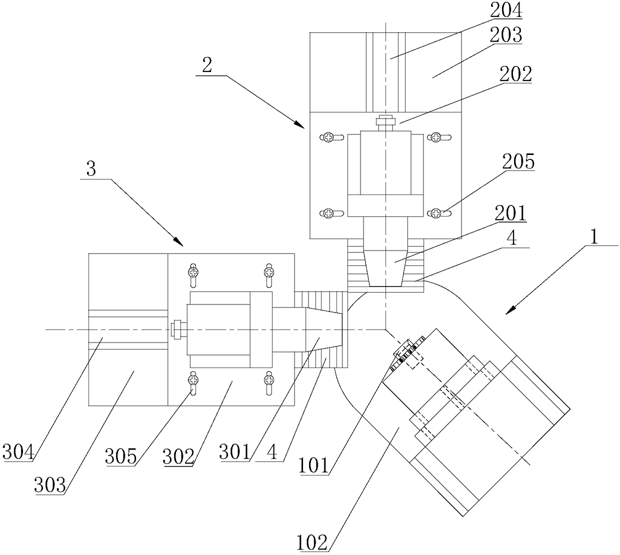
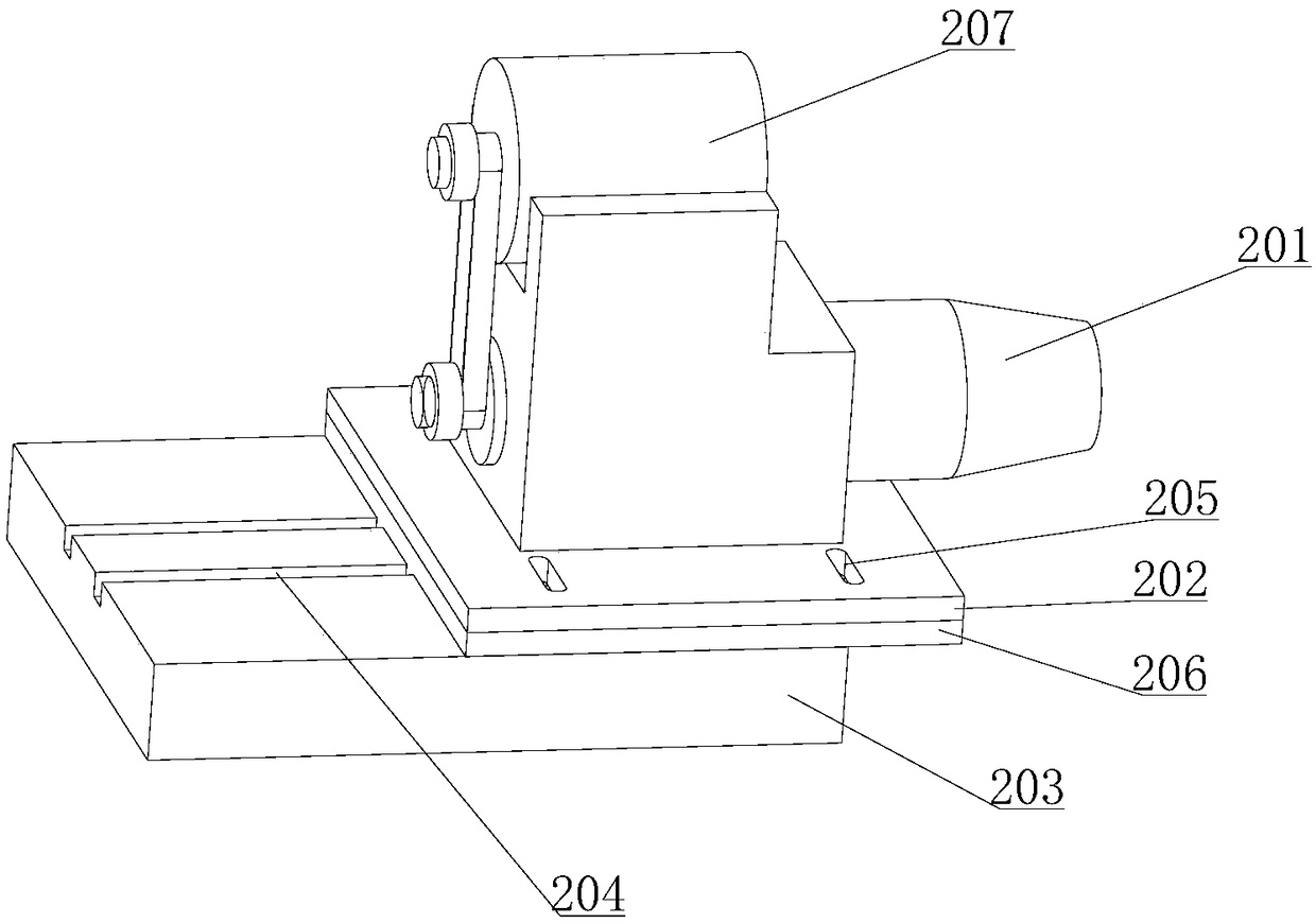
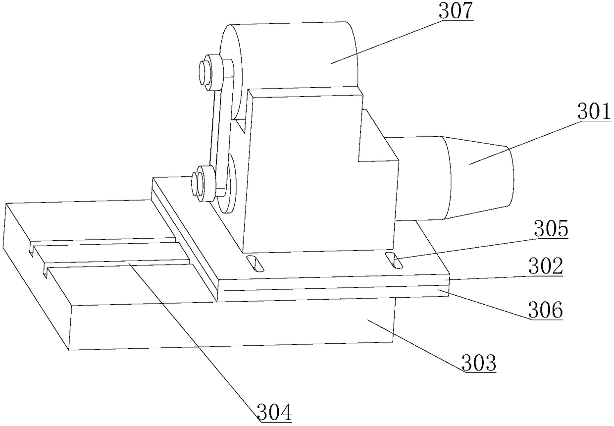
[0044] Such as Figure 1-4 As shown, a method for milling ball cage bell-shaped shells and chamfering includes a fixed part 1, a ball milling part 2, and a chamfering part 3. The fixed part includes a clamping part 101, a first lower base 102, a first The driving device 103 ; the first driving device 103 drives the clamping part 101 to rotate on the first lower base 102 . The clamping part 101 clamps the bell-shaped shell of the ball cage and protrudes in the horizontal direction; The chamfering component includes a chamfering base 303 and a chamfering jig 301 , and the chamfering jig 301 is arranged above the chamfering base 303 . When the clamping part 101 rotates on the first lower base 102 and reaches the first station, the axial direction of the clamping part 101 is parallel to the axial direction of the ballway clamp 201, and the clamping part 101 rotates on the first lower base 102 to reach the second station. During the working position, the axial direction of the cl...

Embodiment 2

[0063] Such as Figure 1-4 As shown, a method for milling ball cage bell-shaped shells and chamfering includes a fixed part 1, a ball milling part 2, and a chamfering part 3. The fixed part includes a clamping part 101, a first lower base 102, a first The driving device 103 ; the first driving device 103 drives the clamping part 101 to rotate on the first lower base 102 . The clamping part 101 clamps the bell-shaped shell of the ball cage and protrudes in the horizontal direction; The chamfering component includes a chamfering base 303 and a chamfering jig 301 , and the chamfering jig 301 is arranged above the chamfering base 303 . When the clamping part 101 rotates on the first lower base 102 and reaches the first station, the axial direction of the clamping part 101 is parallel to the axial direction of the ballway clamp 201, and the clamping part 101 rotates on the first lower base 102 to reach the second station. During the working position, the axial direction of the cl...


PUM


Abstract

The invention provides a method for milling ball grooves and lead angles of ball cage shells. The method comprises a fixing component, a ball groove milling component and a chamfering component, wherein the fixing component comprises a clamping part, a first lower base, a first drive device and a fourth drive device; the fourth drive device drives the clamping part to rotate around a central axis of the clamping part; the ball groove milling component comprises a ball groove clamp and a first guide rail; the chamfering component comprises a chamfering clamp and a second guide rail. The first method comprises the steps as follows: the ball grooves and chamfering angles are milled through back and forth motion of a milling cutter on the ball groove clamp on the guide rail, and the motion of the milling cutter along the direction vertical to the extension direction of the guide rail can be suitable for bell-shaped ball cage shells with different diameters; and the second method comprises the step as follows: the ball grooves and the chamfering angles are milled through side-to-side movement of the milling cutter in the direction vertical to the guide rail. The method has the advantages that only one fixing component is needed for milling the ball grooves and the chamfering angles, and the ball grooves and the chamfering angles of different ball cage shells can be milled through the two methods.

Description

technical field [0001] The invention relates to the technical field of machinery, in particular to a method for milling ball cage bell-shaped shells and chamfering. Background technique [0002] The ball cage bell housing is an important part in the transmission system of the car. Its function is to transmit the power of the engine from the transmission to the two front wheels to drive the car to run at high speed. The outer ball cage is to fix the steel balls in the six windows of a cage between the star-shaped sleeve and the bell-shaped shell. The steel balls are in the star-shaped sleeve and the bell-shaped shell. Half of the positions are used for driving at one time. The smooth surface treatment makes the motion of the universal joint look like a helical gear. The six steel balls respectively push the star-shaped sleeve and the ballway in the bell-shaped housing respectively, and carry out the force provided by the engine. transfer. [0003] During the processing of t...

Claims


Application Information

Patent Timeline
Patent Type & Authority Patents(China)
IPC IPC(8): B23C3/12B23C3/34
CPCB23C3/126B23C3/34
Inventor 戴安其胡超海
Owner 安徽晶隆汽车工业有限公司
Why Eureka
Try Eureka