
Pressure-carrying sealing valve seat

A technology for sealing valves and valve seats, which is applied to valve devices, cocks including cut-off devices, engine components, etc. It can solve the problems of complex process, high cost, and the inability of valves to be repaired and replaced with sealed valve seats under pressure.

Inactive Publication Date: 2017-05-10
ZHEJIANG WEIGUANG VALVE MFG
View PDF5 Cites 2 Cited by
  • Summary
  • Abstract
  • Description
  • Claims
  • Application Information

AI Technical Summary

Problems solved by technology

[0002] For ball valves, when the valve used in the pipeline leaks, it is impossible to repair and replace the sealing valve seat under pressure. Therefore, it is necessary to stop the machine, release the pressure and drain the liquid. The valve sealing seat can only be repaired after the valve is removed from the pipeline. The process is complicated and easy to damage parts. ,higher cost

Method used


Image

  • Pressure-carrying sealing valve seat

Examples


Embodiment

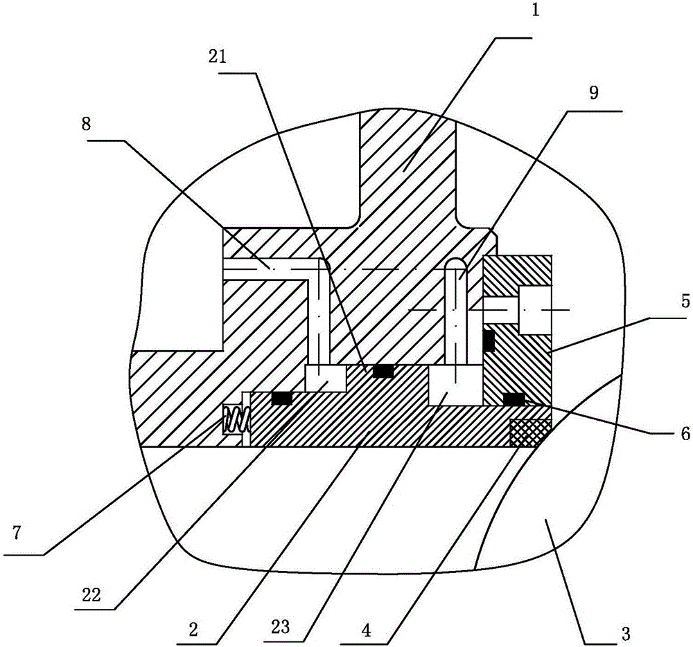
[0013] Embodiment: The present invention seals the valve seat with pressure, as attached figure 1 As shown, it includes a valve seat 2 and a ball 3 arranged in the valve body 1. The valve seat 2 has a hole, and a sealing gasket 4 forms a sealing connection between the hole and the ball 3; the valve seat 2 is slidably arranged in the axial direction. In the valve cavity of the valve body 1; the outer periphery of the valve seat 2 has an annular boss 21, and the outer peripheral surface of the valve seat 2 on both sides of the annular boss 21 and the valve body 1 are surrounded by a first cavity 22 and a second cavity 23 , and the radius of the outer peripheral surface of the valve seat 2 in the second cavity 23 is larger than the radius of the outer peripheral surface of the valve seat 2 in the first cavity 22, so as to overcome the pressure from the spring 7; The first guide hole 8 and the second guide hole 9 communicating with the second cavity 23 .

[0014] A spring 7 is ar...


PUM


Abstract

The invention relates to a pressure-carrying sealing valve seat which comprises a valve seat body arranged in a valve body and a ball body. The valve seat body is provided with a hole. An opening of the hole and the ball body are in sealing connection through a sealing gasket. The valve seat body is axially arranged in a valve cavity of the valve body in a sliding manner. An annular boss is arranged on the periphery of the valve seat body. A first cavity body and a second cavity body are formed in the two sides of the annular boss. A first guiding hole communicating with the first cavity body and a second guiding hole communicating with the second cavity body are formed in the valve body. A piston structure is adopted in the valve seat body and supplies pressure to the two ends of the valve seat body, the valve seat body can slide relative to the ball body, and the sealing specific pressure needed during zero leakage can be achieved during closing; and leakage does not exist on a valve, and the starting torque needed during opening of the valve can be lowered during valve opening.

Description

technical field [0001] The invention relates to a valve seat, in particular to a pressure-sealing valve seat. Background technique [0002] For ball valves, when the valve used in the pipeline leaks, it is impossible to repair and replace the sealing valve seat under pressure. Therefore, it is necessary to stop the machine, release the pressure and drain the liquid. The valve sealing seat can only be repaired after the valve is removed from the pipeline. The process is complicated and easy to damage parts. ,higher cost. Contents of the invention [0003] The main purpose of the present invention is to provide a pressure-tight sealing valve seat, which can be disassembled and repaired under pressure without shutting down the valve to divert liquid to disassemble the valve. [0004] The above-mentioned technical problems of the present invention are mainly solved by the following technical solutions: the pressure-sealing valve seat includes a valve seat and a sphere arrange...

Claims


Application Information

Patent Timeline
Patent Type & Authority Applications(China)
IPC IPC(8): F16K5/08
CPCF16K5/08
Inventor 张士来蔡景兴陈身方
Owner ZHEJIANG WEIGUANG VALVE MFG
Learn More