Device and method for detecting signal circuit delay time in ultrasonic detection device

A detection device, a technology of delay time, applied in the direction of measuring device, measuring ultrasonic/sonic/infrasonic wave, using wave/particle radiation device to transmit sensing components, etc., can solve the error, not double the propagation time 2TD and triple the propagation time 3TD, no echo processing measures, etc.

Active Publication Date: 2017-05-10
GUANGZHOU UNIVERSITY
View PDF8 Cites 8 Cited by
  • Summary
  • Abstract
  • Description
  • Claims
  • Application Information

AI Technical Summary

Problems solved by technology

However, in the ultrasonic flowmeter, it is not twice the propagation time 2TD and three times the propagation time 3TD, because the two ultrasonic transducers are installed obliquely on the pipe wall, and the forward and reverse ultrasonic waves exist twice. The propagation speed of the liquid flow rate is poor, and this is the measurement principle of the ultrasonic flowmeter. The propagation speed of the back and forth is different, and the round-trip propagation time is not twice the propagation time 2TD and three times the propagation time 3TD, so this method has too much error, and the size of the result error is equivalent to the total value of the final liquid flow rate
In addition, the amplitude of the secondary echo or tertiary echo is greatly reduced due to attenuation, and at the same time, there are more clutter caused by multiple reflections and refractions. There is no more accurate echo processing measures in this method, and it is difficult to obtain accurate secondary echoes. secondary echo or triple echo

Method used


Image

  • Device and method for detecting signal circuit delay time in ultrasonic detection device
  • Device and method for detecting signal circuit delay time in ultrasonic detection device

Examples


Embodiment 1

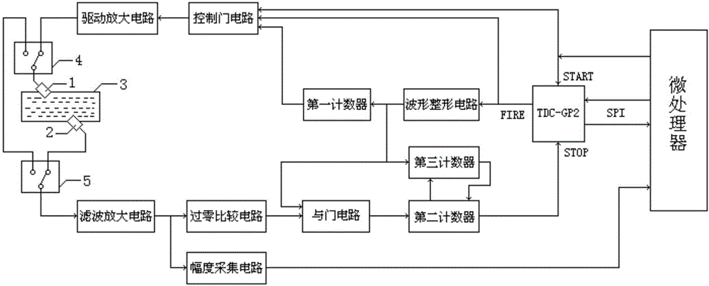
[0058] This embodiment discloses a detection device for the delay time of the signal circuit in the ultrasonic detection device, such as figure 1 As shown, the ultrasonic detection device includes a first ultrasonic probe 1 and a second ultrasonic probe 2 installed obliquely on both sides of the measured object 3, that is, the connecting line between the first ultrasonic probe 1 and the second ultrasonic probe 2 is not vertical When measuring the object; the detection device of the delay time of the signal circuit in this embodiment includes a microprocessor, a picosecond timing chip, a waveform shaping circuit, a control gate circuit, a filter amplifier circuit, a zero-crossing detection circuit, an AND gate circuit, a first A counter, a second counter, a third counter, a first connection changeover switch 4 and a second connection changeover switch 5;

[0059] The first connection switch 4 includes a first contact, a second contact and a third contact, the control end of the...

Embodiment 2

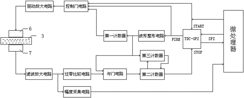
[0091] This embodiment discloses a detection device for the delay time of the signal circuit in the ultrasonic detection device, such as figure 2 As shown, the ultrasonic detection device includes an ultrasonic transmitting probe 6 and an ultrasonic receiving probe 7 vertically installed on both sides of the measured object 3, that is, when the connecting line between the ultrasonic transmitting probe 6 and the ultrasonic receiving probe 7 is perpendicular to the measured object; the signal The circuit delay detection device includes a microprocessor, a picosecond timing chip, a waveform shaping circuit, a control gate circuit, a filter amplifier circuit, a zero-crossing detection circuit, an AND gate circuit, a first counter, a second counter and a third counter.

[0092] The data IO port of the picosecond-level timing chip is connected to the microprocessor, and the control command sent by the microprocessor is received through the data IO port and the timing result is sent ...


PUM


Abstract

The invention discloses a device and a method for detecting signal circuit delay time in an ultrasonic detection device. The method for detecting the signal circuit delay time comprises a microprocessor, a picosecond level timing chip, a wave shaping circuit, a control gate circuit, a filter amplifier circuit, a zero cross detection circuit, an AND gate circuit, a first counter, a second counter, a third counter, a first connecting change-over switch and a second connecting change-over switch. The total time T1, T2 and T3 from transmitting to receiving a primary ultrasonic echo signal, a secondary ultrasonic echo signal and a ternary ultrasonic echo signal are respectively calculated via the picosecond level timing chip, and the delay time phi=T1+T2-T3 of a signal in a circuit is calculated via the T1, T2 and T3. Three discrimination technologies of wave contrast, counting and time limitation are adopted for the three times of ultrasonic echo recognition, so that clutter interference is eliminated, the accuracy of echo is ensured, and the delay time of the ultrasonic signal in the circuit can be accurately obtained.

Description

technical field [0001] The invention relates to a related technology of ultrasonic detection equipment, in particular to a detection device and method for delay time of a signal circuit in an ultrasonic detection device. Background technique [0002] Ultrasonic detection technology is widely used, such as relative blood volume detection based on ultrasound, ultrasonic milk concentration detection, ultrasonic liquid concentration detection, ultrasonic flowmeter, ultrasonic thickness measurement, etc., the basic principle is to use the speed characteristics of ultrasonic propagation in the measured material To detect the composition characteristics of the material, the ultrasonic wave is usually passed through the measured object, and then the relevant characteristics of the measured object are obtained according to the time information of the ultrasonic echo. The most important parameter of these measurements is the propagation time of the ultrasonic wave in the measured objec...

Claims


Application Information

Patent Timeline
Patent Type & Authority Applications(China)
IPC IPC(8): G01D5/48G01D18/00G01H17/00
CPCG01D5/48G01D18/00G01H17/00
Inventor 蒋顺忠
Owner GUANGZHOU UNIVERSITY
Why Eureka
Try Eureka