


Quick Research
Generate reliable direction feasibility study reports for your R&D in just a few steps.

Technical Q&A
Discover and master advanced knowledge NOW. Basics, ideas, possibilities, all at once.

Find Solutions
As an expert in R&D theories, this can generate solutions to your technical problems instantly.

Evaluate Feasibility
Analyze your overall solution with one click, know your potential R&D risks in advance.

Monitor Landscape
Get weekly tech updates, stay abreast of the latest tech innovations and key insights.
Detection jig and method for correcting scanning sensors of dry etcher
A technology for detecting fixtures and dry etching, applied in the field of scanning sensors, can solve the problems of glass substrate damage and affecting operation time, and achieve the effect of avoiding normal operation, simplifying the correction process, and shortening the correction time.
- Summary
- Abstract
- Description
- Claims
- Application Information
AI Technical Summary
Problems solved by technology
Method used
Image

Examples
Embodiment 1
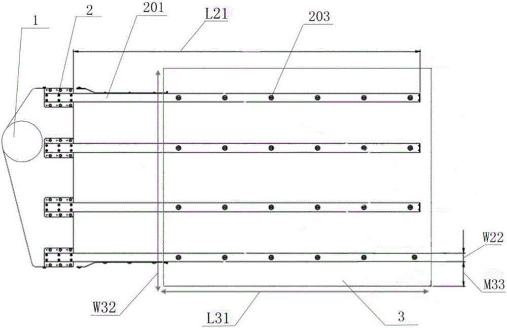
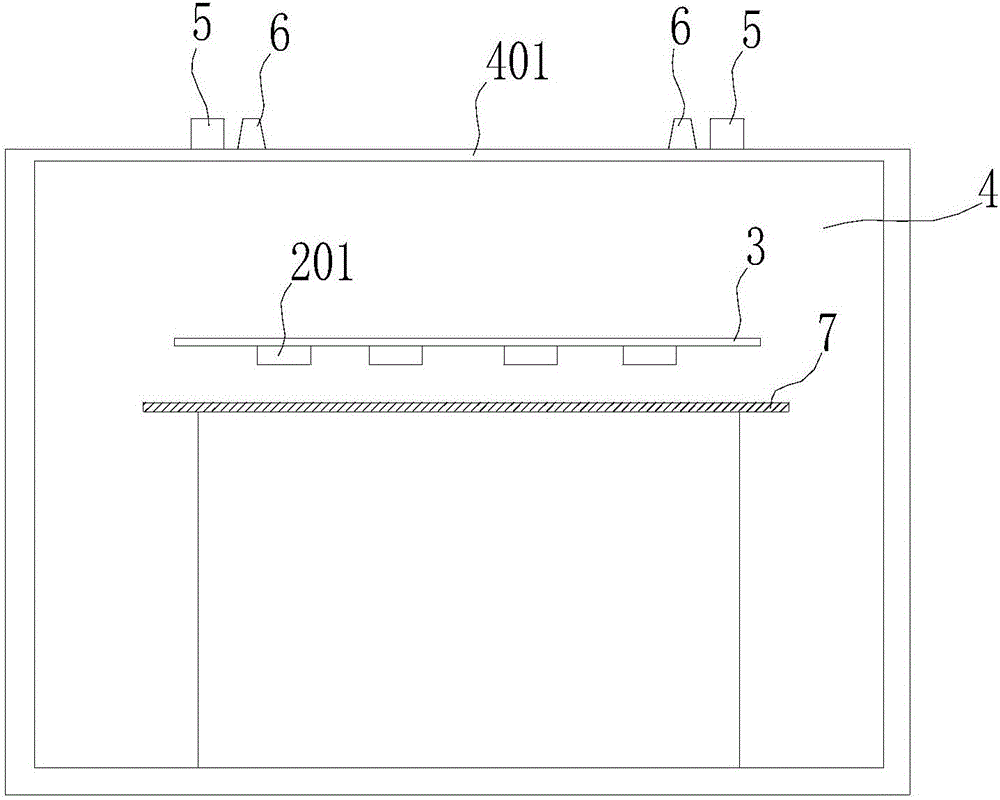
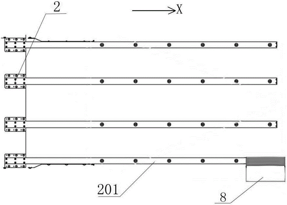
[0039] Please also refer to Figure 3 to Figure 7 , image 3 It is a schematic diagram of embodiment 1 of the detection jig for correcting the scanning sensor of the dry etching machine according to the present invention, Figure 4 It is a schematic diagram of the detection jig for correcting the detection jig of the scanning sensor of the dry etching machine in Embodiment 1 of the present invention entering the transmission cavity of the dry etching machine, Figure 5 yes Figure 4 Enlarged view of part A in, Figure 6 It is a perspective view of the transparent detection plate in Embodiment 1 of the detection fixture for correcting the scanning sensor of the dry etching machine according to the present invention, Figure 7 It is a schematic diagram of another arrangement of the transparent detection board on the running carrier in Embodiment 1 of the detection jig for correcting the scanning sensor of the dry etching machine according to the present invention.
[0040] T...
Embodiment 2
[0052] see Figure 8 , Figure 8 It is a perspective view of the transparent detection plate in Embodiment 2 of the detection jig for correcting the scanning sensor of the dry etching machine according to the present invention. In this embodiment, barbs 11 are provided on the side of the two side plates 10 of the detection fixture away from the transparent detection plate 8. The purpose of setting the barbs 11 is to make the slot 801 clamped on the running carrier of the detection fixture. Faster, to ensure the horizontal setting of the transparent detection board 8, the transparent detection board of this type of structure needs to be sleeved by the end of the branch arm of the running carrier, and the transparent detection board 8 can be hung upside down on the running carrier of the detection fixture .
Embodiment 3
[0054] see Figure 9 , Figure 9 It is a schematic diagram of Embodiment 3 of the detection jig for correcting the scanning sensor of the dry etching machine according to the present invention. In this embodiment, the length of the transparent detection plate 8 is shorter than the length of the glass substrate detected by the dry etching machine. When the scanning sensor of the dry etching machine detects the glass substrate, the glass substrate basically covers the entire running carrier 2, that is, 4 and The branch arms 201 are all under the glass substrate, but the transparent detection plate 8 is only about 1 / 50 of the area of the glass substrate. The width W3 of the transparent detection plate 8 ranges from 100 mm to 300 mm, and the range of its length W4 is 300 mm to 500 mm. The thickness of the transparent detection plate 8 is 1mm, and the area of the transparent detection plate is small, which is convenient for taking and correcting. The transparent detection pla...
PUM
| Property | Measurement | Unit |
|---|---|---|
| thickness | aaaaa | aaaaa |
| width | aaaaa | aaaaa |
| length | aaaaa | aaaaa |
Abstract
Description
Claims
Application Information
 - R&D Engineer
- R&D Manager
- IP Professional
- Industry Leading Data Capabilities
- Powerful AI technology
- Patent DNA Extraction
Browse by: Latest US Patents, China's latest patents, Technical Efficacy Thesaurus, Application Domain, Technology Topic, Popular Technical Reports.
© 2024 PatSnap. All rights reserved.Legal|Privacy policy|Modern Slavery Act Transparency Statement|Sitemap|About US| Contact US: help@patsnap.com