Deep UV optical system confocal alignment device and method

An optical system and alignment device technology, applied in optics, optical components, testing optical performance, etc., can solve problems such as large residual error, and achieve the effect of high-precision confocal alignment

Active Publication Date: 2017-05-10
INST OF MICROELECTRONICS CHINESE ACAD OF SCI
View PDF5 Cites 13 Cited by
  • Summary
  • Abstract
  • Description
  • Claims
  • Application Information

AI Technical Summary

Problems solved by technology

The document "Confocal position alignment in high precision wavefront error metrology using Shack‐Hartmann wavefront sensor" (Proc. SPIE, 2016, 9780: 97801N) uses computer-aided adjustme

Method used


Image

  • Deep UV optical system confocal alignment device and method
  • Deep UV optical system confocal alignment device and method
  • Deep UV optical system confocal alignment device and method

Examples


Embodiment Construction

[0035] Exemplary embodiments of the present disclosure will be described in more detail below with reference to the accompanying drawings. Although exemplary embodiments of the present disclosure are shown in the drawings, it should be understood that the present disclosure may be embodied in various forms and should not be limited by the embodiments set forth herein. Rather, these embodiments are provided for more thorough understanding of the present disclosure and to fully convey the scope of the present disclosure to those skilled in the art.

[0036] Embodiments of the present invention will be described in detail below in conjunction with the accompanying drawings.

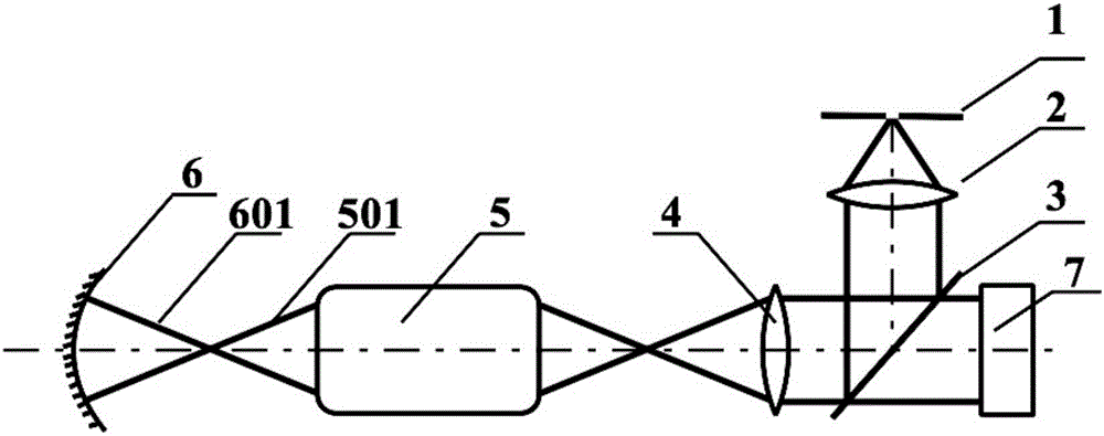
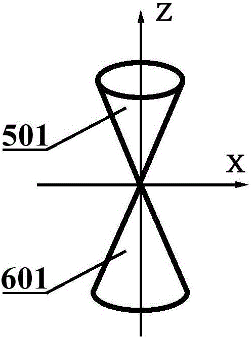
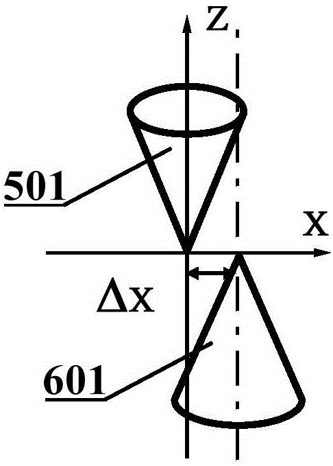
[0037] Such as figure 1 Shown is the device used in the present invention, including small hole plate (1), collimating objective lens (2), beam splitter plate (3), conjugate imaging objective lens (4), deep ultraviolet optical system (5), deep The ultraviolet optical system converges the light beam (501), ...


PUM


Abstract

The invention discloses a deep UV optical system confocal alignment device and method. The device comprises an orifice plate (1), a collimator lens (2), a beam splitter plate (3), a conjugate imaging object lens (4), a deep UV optical system (5), a deep UV optical system converging beam (501), a spherical reflector (6), a spherical reflector converging beam (601), and a Shack-Hartmann wavefront sensor (7). The confocal aligning adjustment of the deep UV optical system and the spherical reflector is carried out by an artificial neural network method, a confocal aligning model is adopted to acquire samples, and the relation between Zernike polynomial coefficients and system misalignment is established by neural network training to achieve fast and high-precision confocal alignment.

Description

technical field [0001] The invention relates to the technical field of optical adjustment, in particular to a confocal alignment device and method for a deep ultraviolet optical system. Background technique [0002] Deep ultraviolet optical systems, such as projection optical systems for semiconductor microlithography, observation systems used in the semiconductor industry, ultraviolet optical systems used in the manufacture of micro-nano structures, etc., usually have extremely small wave aberrations, such as The systematic wave aberration of projection lithography objective lens is on the order of several nanometers. Therefore, wave aberration detection must be carried out in all links of deep ultraviolet optical system processing, integration and work. In the detection of wave aberration of deep ultraviolet optical system based on dual-channel Shaker-Hartmann method, the confocal alignment accuracy of deep ultraviolet optical system and spherical mirror is a key factor a...

Claims


Application Information

Patent Timeline
IPC IPC(8): G02B27/00G01M11/02
CPCG01M11/02G02B27/00G02B27/0012
Inventor 卢增雄齐月静王宇苏佳妮齐威杨光华周翊孟庆宾
Owner INST OF MICROELECTRONICS CHINESE ACAD OF SCI
Why Eureka
Try Eureka