Control circuit, driving method and display device for display panel

A display panel and control circuit technology, applied to static indicators, instruments, etc., can solve the problems of grid signal time extension, leakage area increase, grid line load capacitance increase, etc., to ensure high aperture ratio frame and ensure charging time , Reduce the effect of leakage area

Active Publication Date: 2020-04-24
BOE TECH GRP CO LTD
View PDF9 Cites 0 Cited by
  • Summary
  • Abstract
  • Description
  • Claims
  • Application Information

AI Technical Summary

Problems solved by technology

[0003] The main purpose of the present invention is to provide a control circuit, a driving method and a display device for a display panel, which solve the problem that in the prior art, when the gate line is opened, the shielding electrode arranged above the gate line is still connected to the common electrode, and Since the load capacitance of the gate line increases significantly after the gate line is blocked, the delay of the gate line drive also increases greatly, resulting in a longer time for charging and discharging the gate signal, making it impossible to meet the pixel charging requirements when applied to ultra-high resolution, and leakage The area increases, and the problem that the pixel high aperture ratio frame cannot be guaranteed

Method used


Image

  • Control circuit, driving method and display device for display panel
  • Control circuit, driving method and display device for display panel
  • Control circuit, driving method and display device for display panel

Examples


specific Embodiment approach

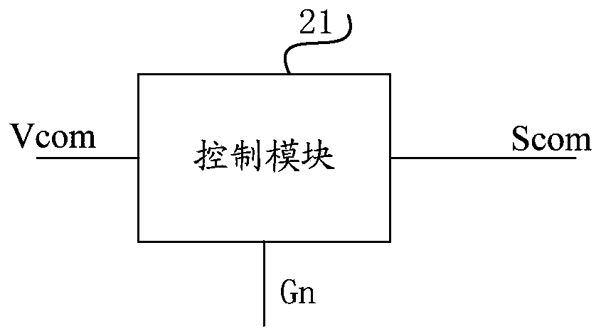
[0058] According to another specific embodiment, the control module includes:

[0059] The controller is respectively connected with the gate drive signal output end of the corresponding row, the gate drive signal output end of the adjacent upper row and the gate drive signal output end of the adjacent next row, and is used for when the potential of the gate drive signal of the corresponding row is the first A second level is output when the potential of the gate driving signal of the adjacent upper row is the first level or the potential of the gate driving signal of the adjacent next row is the first level. When the gate driving signal of the corresponding row is at the first level , outputting a first level when both the gate drive signal of the adjacent upper row and the gate drive signal of the adjacent next row are the first level; and,

[0060] A switching transistor, the control electrode is connected to the output end of the controller, the first electrode is connecte...


PUM


Abstract

The present invention provides a control circuit for a display panel, a driving method of a display panel, and a display device. The control circuit for the display panel is used for controlling the display panel, wherein the display panel includes shielding electrodes, gate lines and a gate driving circuit, wherein corresponding shielding electrodes are arranged above a row of gate lines and are used for blocking the gate lines; the control circuit for the display panel includes a shielding electrode control unit; the shielding electrodes are connected with a common electrode through the shielding electrode control unit; and the shielding electrode control unit is used for controlling the corresponding the shielding electrodes to be in floating states when the gate lines are switched on. With the control circuit of the invention adopted, time required by the gate signals lines to perform charging and discharging can be effectively decreased, and the charging time of pixels can be ensured, electric leakage areas can be reduced, and the high-aperture ratio frame of the pixels can be ensured.

Description

technical field [0001] The present invention relates to the technical field of display panel control, and in particular, to a control circuit, a driving method and a display device for a display panel. Background technique [0002] In order to increase the pixel aperture ratio and reduce light leakage around the gate lines, shield electrodes are used to shield part of the gate lines. In the prior art, when the gate line is turned on, the shielding electrode disposed above the gate line is still connected to the common electrode. However, after the gate line is shielded, the load capacitance of the gate line is greatly increased, and the driving delay of the gate line is also greatly increased. The time required for the charging and discharging of the polar signal is prolonged, so that when applied to ultra-high resolution, it cannot meet the needs of pixel charging, and the leakage area increases, which cannot guarantee the requirements of the high aperture ratio frame of th...

Claims


Application Information

Patent Timeline
Patent Type & Authority Patents(China)
IPC IPC(8): G09G3/20
CPCG09G3/20
Inventor 商广良韩明夫韩承佑林允植董学
Owner BOE TECH GRP CO LTD
Why Eureka
Try Eureka