
Loudspeaker horn

A loudspeaker and horn technology, which is applied in the field of loudspeaker horns, can solve the problem that the lower limit frequency of the horn of the high-frequency driver cannot meet the needs, and achieve the effects of avoiding off-axis frequency response peaks and valleys, stable sound wave output, and increased intensity

Pending Publication Date: 2017-05-10
唐永均
View PDF11 Cites 4 Cited by
  • Summary
  • Abstract
  • Description
  • Claims
  • Application Information

AI Technical Summary

Problems solved by technology

The horns used in the treble drivers on the market generally do not have phase plugs, or only use simple bullet phase plugs, and the bullet phase plugs only have a certain positive effect on the circumferentially uniform "eight"-shaped horn shell. When the horn shell is In other shapes, it is far from meeting the needs
[0006] In addition, in the prior art, the upper limit frequency of the horn of the high-frequency driver is only 16.5kHz, and there is still a certain distance from the upper limit frequency requirement of 20kHz for high-quality requirements; the lower limit frequency of the horn of the high-frequency driver cannot meet the needs

Method used


Image

  • Loudspeaker horn
  • Loudspeaker horn
  • Loudspeaker horn

Examples


Embodiment Construction

[0032] Embodiments of the present invention will be described in detail below in conjunction with the accompanying drawings.

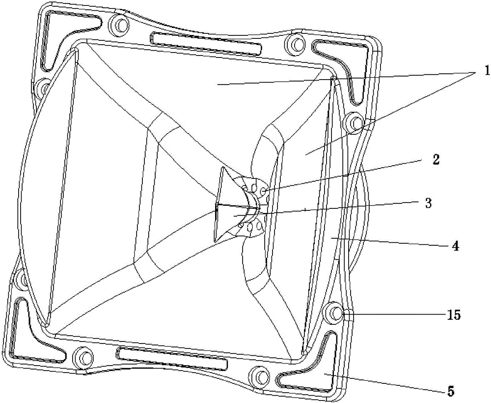
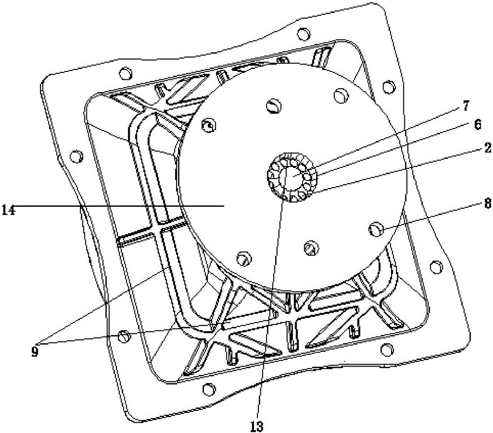
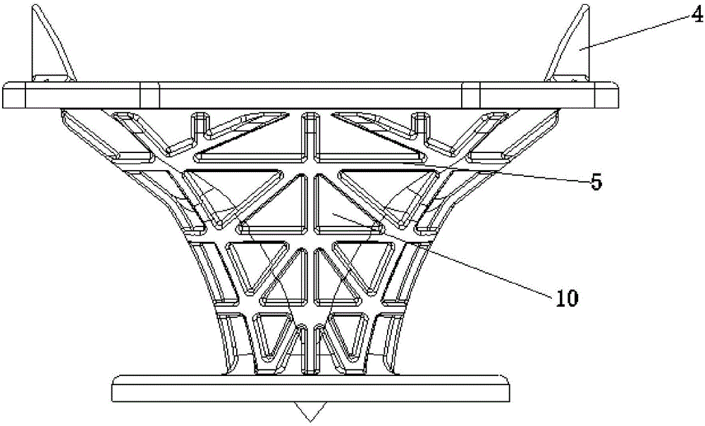
[0033] A loudspeaker horn, comprising a trumpet-shaped housing 10, the small end of the housing 10 is connected to the mounting base 14, and the large end is a face plate, and the housing 12 includes a throat 11 connected with the horn driver, and the throat 11 is Several manifolds 2 are fixedly arranged, and the manifolds 2 communicate with the two ports of the throat pipe 11 . By setting the manifold 2 in the present invention, the upper limit frequency of the horn can be greatly improved.

[0034] Preferably, the horn further includes a deflector 7 for splitting the sound waves of the loudspeaker high frequency driver 16 . The arrangement of the deflector 7 can shunt the sound generated by the high-frequency driver 16, so that no sound focusing phenomenon occurs. The loudspeaker high-frequency driver is connected to the mounting base and is locate...


PUM


Abstract

The invention relates to the technical field of sound box products, and particularly relates to a loudspeaker horn. The loudspeaker horn comprises a horn-shaped shell; the small end of the shell is connected with a mounting seat and the large end is a disc; the shell comprises a throat pipe connected with the mounting seat; the throat pipe is internally fixed with a plurality of manifolds; and the manifolds are communicated with two ports of the throat pipe. The upper limit frequency of the horn is greatly enhanced.

Description

technical field [0001] The invention relates to the technical field of audio products, in particular to a loudspeaker horn. Background technique [0002] In traditional speaker system design, it is often encountered that a high-frequency driver and a low-frequency unit are used to form a two-way full-range speaker. The high-frequency driver will be equipped with a horn to cooperate with the low-frequency unit to make the high-frequency driver heavy. The released sound waves are projected into the use space. [0003] According to the acoustic theory, sound waves have sound wave reflection and sound wave interference phenomena. When the high-frequency driver diaphragm moves back and forth as a piston, the resulting sound waves radiate outward through the throat of the horn to form sound. However, not all the sound waves are directly diffused outwards, and some of the sound waves will be cross-reflected on the reflective surface of the horn before being sent to the listener's ...

Claims


Application Information

Patent Timeline
Patent Type & Authority Applications(China)
IPC IPC(8): H04R1/28
CPCH04R1/2819
Inventor 唐永均
Owner 唐永均
Learn More